4. Infrastructure Capabilities, Measurements and Catalogue
4.1. Capabilities and performance measurements
This section describes the capabilities provided by the Cloud Infrastructure, and the performance measurements (PMs) generated by the Cloud Infrastructure (that is, without the use of external instrumentation).
The capability and PM identifiers conform to the following schema:
4.1.1. Exposed versus internal
The following definitions specify the context of the Cloud Infrastructure resources, capabilities and performance measurements (PMs).
Exposed: This refers to any object (for example, resource discovery/configuration/consumption, platform telemetry, interface, and so on) that exists in, or pertains to, the domain of the Cloud Infrastructure and is made visible, or exposed to, a workload. When an object is exposed to a given workload, the scope of visibility within a given workload is at the discretion of the workload’s designer. From an infrastructure perspective, the infra-resident object is simply being exposed to one or more virtual environments, or workloads. It is the responsibility of the kernel, or the supervisor or executive within the resource instance (VM or container) to control how, when, and where the object is further exposed within the resource instance, with regard to permissions, security, and so on. An object is, by definition, visible within its domain of origin.
Internal: This is the opposite of exposed. Objects are exclusively available for use within the Cloud Infrastructure.
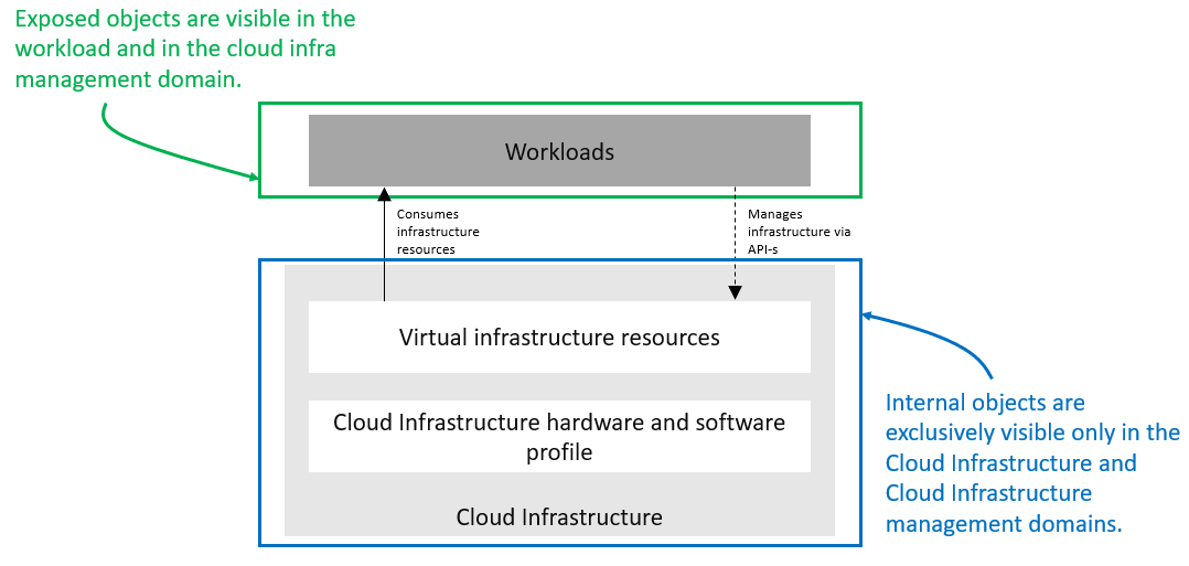
Figure 4.1 Exposed versus internal scope
As illustrated in the figure above, objects designated as internal are only visible within the area inside the blue oval (the Cloud Infrastructure), and only when the entity accessing the object has the appropriate permissions. Objects designated as exposed are potentially visible from both the area within the green oval (the Workloads), as well as from within the Cloud Infrastructure, again provided the entity accessing the object has the appropriate permissions.
Note
The figure above indicates the areas from where the objects are visible. It is not intended to indicate where the objects are instantiated. For example, the virtual resources are instantiated within the Cloud Infrastructure (the blue area), but are exposed, and are therefore visible to the workloads within the green area.
4.1.2. Exposed infrastructure capabilities
This section describes a set of exposed Cloud Infrastructure capabilities and performance measurements. These capabilities and PMs are well-known to workloads, as they provide the capabilities on which the workloads rely.
Note
The Cloud Infrastructure capabilities and measurements are expected to expand over time, as more capabilities are added, and the technology improves and matures.
4.1.2.1. Exposed resource capabilities
Table 4-1 below shows resource capabilities of the Cloud Infrastructure available to the workloads.
Ref |
Cloud Infrastructure capability |
Unit |
Definition/Notes |
|---|---|---|---|
e.cap.001 |
# vCPU |
number |
The maximum number of vCPUs that can be assigned to a single VM or Pod (1). |
e.cap.002 |
RAM Size |
MB |
The maximum memory, in MB, that can be assigned to a single VM or Pod by the Cloud Infrastructure (2). |
e.cap.003 |
Total per-instance (ephemeral) storage |
GB |
The maximum storage, in GB, that can be assigned to a single VM or Pod by the Cloud Infrastructure. |
e.cap.004 |
# Connection points |
number |
The maximum number of connection points that can be assigned to a single VM or Pod by the Cloud Infrastructure. |
e.cap.005 |
Total external (persistent) storage |
GB |
The maximum storage, in GB, that can be attached or mounted to a VM or Pod by the Cloud Infrastructure. |
Table 4-1: Exposed resource capabilities of the Cloud Infrastructure
In a Kubernetes-based environment, this means the CPU limit of a pod.
In a Kubernetes-based environment, this means the memory limit of a pod.
4.1.2.2. Exposed performance optimisation capabilities
Table 4-2 lists the performance optimisation capabilities exposed to the workloads by the Cloud Infrastructure.
Ref |
Cloud Infrastructure capability |
Unit |
Definition/Notes |
|---|---|---|---|
e.cap.006 |
CPU pinning |
Yes/No |
Indicates if the Cloud Infrastructure supports CPU pinning. |
e.cap.007 |
NUMA alignment |
Yes/No |
Indicates if the Cloud Infrastructure supports NUMA alignment. |
e.cap.008 |
IPSec Acceleration |
Yes/No |
IPSec acceleration. |
e.cap.009 |
Crypto Acceleration |
Yes/No |
Crypto acceleration. |
e.cap.010 |
Transcoding Acceleration |
Yes/No |
Transcoding acceleration. |
e.cap.011 |
Programmable Acceleration |
Yes/No |
Programmable acceleration. |
e.cap.012 |
Enhanced Cache Management |
Yes/No |
If supported, L=Lean; E=Equal; X=eXpanded. L and X cache policies require CPU pinning to be active. |
e.cap.013 |
SR-IOV over PCI-PT |
Yes/No |
Traditional SR-IOV. These capabilities generally require hardware-dependent drivers to be injected into the workloads. |
e.cap.014 |
GPU/NPU |
Yes/No |
Hardware coprocessor. These capabilities generally require hardware-dependent drivers to be injected into the workloads. |
e.cap.015 |
SmartNIC |
Yes/No |
Network acceleration. |
e.cap.016 |
FPGA/other Acceleration HW |
Yes/No |
These capabilities generally require hardware-dependent drivers to be injected into the workloads. |
e.cap.023 |
Huge pages |
Yes/No |
Indicates if the Cloud Infrastructure supports huge pages. |
e.cap.024 |
CPU allocation ratio |
Yes/No |
N:1: Denotes the number of virtual cores per physical core. It is also known as the CPU overbooking ratio. |
e.cap.025 |
AF_XDP |
Yes/No |
Indicates whether or not the Cloud Infrastructure supports AF_XDP. |
Table 4-2: Exposed performance optimisation capabilities of the Cloud Infrastructure
Enhanced Cache Management is a compute performance enhancer that applies a cache management policy to the socket hosting a given virtual compute instance, provided the associated physical CPU microarchitecture supports it. A cache management policy can be used to specify the static allocation of cache resources to cores within a socket. The “Equal” policy distributes the available cache resources equally across all of the physical cores in the socket. The “eXpanded” policy provides additional resources to the core pinned to a workload that has the “X” attribute applied. The “Lean” attribute can be applied to workloads which do not realise significant benefit from a marginal cache size increase and are therefore willing to relinquish unneeded resources.
In addition to static allocation, an advanced Reference Architecture implementation can implement dynamic cache management control policies, operating with tight (~ms) or standard (tens of seconds) control loop response times, thereby achieving higher overall performance for the socket.
4.1.2.3. Exposed monitoring capabilities
Monitoring capabilities are used for the passive observation of workload-specific traffic traversing the Cloud Infrastructure. As with all capabilities, monitoring may be unavailable or intentionally disabled for security reasons in a given Cloud Infrastructure deployment. If this functionality is enabled, it must be subject to strict security policies. For further details, see the Reference Model Security chapter.
Table 4-3 shows the possible monitoring capabilities available from the Cloud Infrastructure for the workloads.
Ref |
Cloud Infrastructure capability |
Unit |
Definition/notes |
|---|---|---|---|
e.cap.017 |
Monitoring of L2-7 data |
Yes/No |
Ability to monitor L2-L7 data from the workload. |
Table 4-3: Exposed monitoring capabilities of the Cloud Infrastructure
Table 4-4: Place holder
4.1.3. Internal infrastructure capabilities
This section covers a list of implicit Cloud Infrastructure capabilities and measurements. These capabilities and metrics are hidden from the workloads (that is, workloads may not know about them). However, they will impact the overall performance and capabilities of a given Cloud Infrastructure solution.
Note
The implicit Cloud Infrastructure capabilities and metrics are expected to evolve with time, as more capabilities are added as technology improves and matures.
4.1.3.1. Internal resource capabilities
Table 4-5 shows the resource capabilities of the Cloud Infrastructure. These include the capabilities offered to the workloads and resources consumed internally by the Cloud Infrastructure.
Ref |
Cloud Infrastructure capability |
Unit |
Definition/notes |
|---|---|---|---|
i.cap.014 |
CPU cores consumed by the Cloud Infrastructure overhead on a worker (compute) node |
% |
The ratio, expressed as a percentage, of cores consumed by the Cloud Infrastructure components (including the host OS) in a compute node to the total number of cores available. |
i.cap.015 |
Memory consumed by the Cloud Infrastructure overhead on a worker (compute) node |
% |
The ratio, expressed as a percentage, of memory consumed by the Cloud Infrastructure components (including host OS) in a worker (compute) node to the total available memory. |
Table 4-5: Internal resource capabilities of the Cloud Infrastructure
4.1.3.2. Internal SLA capabilities
Table 4-6 below shows the Service-Level Agreement (SLA) capabilities of the Cloud Infrastructure. These include Cloud Infrastructure capabilities required by workloads as well as required internal to Cloud Infrastructure. Application of these capabilities to a given workload is determined by its Cloud Infrastructure Profile.
Ref |
Cloud Infrastructure Capability |
Unit |
Definition/Notes |
|---|---|---|---|
i.cap.017 |
Connection point QoS |
Yes/No |
QoS enablement of the connection point (vNIC or interface) |
Table 4-6: Internal SLA capabilities to Cloud Infrastructure
4.1.3.3. Internal Performance Measurement Capabilities
Table 4-8 shows possible performance measurement capabilities for the Cloud Infrastructure. The availability of these capabilities will be determined by the Cloud Infrastructure Profile used by the workloads. These measurements or events should be collected and monitored by monitoring tools.
Ref |
Cloud Infrastructure Capability |
Unit |
Definition/Notes |
|---|---|---|---|
i.pm.001 |
Host CPU usage |
nanoseconds |
Per Compute node. It maps to ETSI GS NFV-TST 008 V3.5.1 [21] processor usage metric (Cloud Infrastructure internal). |
i.pm.002 |
Virtual compute resource (vCPU) usage |
nanoseconds |
Per VM or Pod. It maps to ETSI GS NFV-IFA 027 v2.4.1 [22] Mean vCPU usage and Peak vCPU usage (Cloud Infrastructure external). |
i.pm.003 |
Host CPU utilisation |
% |
Per Compute node. It maps to ETSI GS NFV-TST 008 V3.5.1 [21] processor usage metric (Cloud Infrastructure internal). |
i.pm.004 |
Virtual compute resource (vCPU) utilisation |
% |
Per VM or Pod. It maps to ETSI GS NFV-IFA 027 v2.4.1 [22] Mean vCPU usage and Peak vCPU usage (Cloud Infrastructure external). |
i.pm.005 |
Network metric, Packet count |
Number of packets |
Number of successfully transmitted or received packets per physical or virtual interface, as defined in ETSI GS NFV-TST 008 V3.5.1 [21] |
i.pm.006 |
Network metric, Octet count |
8-bit bytes |
Number of 8-bit bytes that constitute successfully transmitted or received packets per physical or virtual interface, as defined in ETSI GS NFV-TST 008 V3.5.1 [21] |
i.pm.007 |
Network metric, Dropped Packet count |
Number of packets |
Number of discarded packets per physical or virtual interface, as defined in ETSI GS NFV-TST 008 V3.5.1 [21] |
i.pm.008 |
Network metric, Errored Packet count |
Number of packets |
Number of erroneous packets per physical or virtual interface, as defined in ETSI GS NFV-TST 008 V3.5.1 [21] |
i.pm.009 |
Memory buffered |
KiB |
Amount of temporary storage for raw disk blocks, as defined in ETSI GS NFV-TST 008 V3.5.1 [21] |
i.pm.010 |
Memory cached |
KiB |
Amount of RAM used as cache memory, as defined in ETSI GS NFV-TST 008 V3.5.1 [21] |
i.pm.011 |
Memory free |
KiB |
Amount of RAM unused, as defined in ETSI GS NFV-TST 008 V3.5.1 [21] |
i.pm.012 |
Memory slab |
KiB |
Amount of memory used as a data structure cache by the kernel, as defined in ETSI GS NFV-TST 008 V3.5.1 [21] |
i.pm.013 |
Memory total |
KiB |
Amount of usable RAM, as defined in ETSI GS NFV-TST 008 V3.5.1 [21] |
i.pm.014 |
Storage free space |
Bytes |
for a given storage system, amount of unused storage as defined in ETSI GS NFV-TST 008 V3.5.1 [21] |
i.pm.015 |
Storage used space |
Bytes |
for a given storage system, amount of storage used as defined in ETSI GS NFV-TST 008 V3.5.1 [21] |
i.pm.016 |
Storage reserved space |
Bytes |
for a given storage system, amount of storage reserved as defined in ETSI GS NFV-TST 008 V3.5.1 [21] |
i.pm.017 |
Storage Read latency |
Milliseconds |
for a given storage system, average amount of time to perform a Read operation as defined in ETSI GS NFV-TST 008 V3.5.1 [21] |
i.pm.018 |
Storage Read IOPS |
operations per second |
for a given storage system, average rate of performing Read operations as defined in ETSI GS NFV-TST 008 V3.5.1 [21] |
i.pm.019 |
Storage Read Throughput |
Bytes per second |
for a given storage system, average rate of performing Read operations as defined in ETSI GS NFV-TST 008 V3.5.1 |
i.pm.020 |
Storage Write latency |
Milliseconds |
for a given storage system, average amount of time to perform a Write operation as defined in ETSI GS NFV-TST 008 V3.5.1 |
i.pm.021 |
Storage Write IOPS |
operations per second |
for a given storage system, average rate of performing Write operations as defined in ETSI GS NFV-TST 008 V3.5.1 [21] |
i.pm.022 |
Storage Write Throughput |
Bytes per second |
for a given storage system, average rate of performing Write operations as defined in ETSI GS NFV-TST 008 V3.5.1 [21] |
i.pm.023 |
Host power utilization |
Watt (Joule/s) |
Real-time electrical power used by a node (1) |
i.pm.024 |
Host energy consumption |
Watt.hour (Joule) |
Electrical energy consumption of a node since the related counter last reset (2) |
i.pm.025 |
CPU power utilization |
Watt (Joule/s) |
Real-time electrical power used by the processor(s) of a node (1) |
i.pm.026 |
CPU energy consumption |
Watt.hour (Joule) |
Electrical energy consumption of the processor(s) of a node since the related counter last reset (2) |
i.pm.027 |
PCIe device power utilization |
Watt (Joule/s) |
Real-time electrical power used by a specific PCI device of a node (1) |
i.pm.028 |
PCIe device energy consumption |
Watt.hour (Joule) |
Electrical energy consumption of a specific PCI device of a node since the related counter last reset (2) |
i.pm.029 |
RAM power utilization |
Watt (Joule/s) |
Real-time electrical power used by the memory of a node (1) |
i.pm.030 |
RAM energy consumption |
Watt.hour (Joule) |
Electrical energy consumption of the memory of a node since the related counter last reset (2) |
i.pm.031 |
Disk power utilization |
Watt (Joule/s) |
Real-time electrical power used by a specific storage device of a node (1) |
i.pm.032 |
Disk energy consumption |
Watt.hour (Joule) |
Electrical energy consumption of a specific storage device of a node since the related counter last reset (2) |
i.pm.033 |
Hugepages pool total |
Integer |
the number of Hugepages currently configured in the pool, which is the total of pages available, as defined in ETSI GS NFV-TST 008 V3.5.1 [21] |
i.pm.034 |
Hugepages used |
Integer |
the number of used pages in the Hugepage Pool, as defined in ETSI GS NFV-TST 008 V3.5.1 [21] |
i.pm.035 |
Hugepages free |
Integer |
the number of free pages in the Hugepage Pool, as defined in ETSI GS NFV-TST 008 V3.5.1 [21] |
Table 4-8: Internal Measurement Capabilities of Cloud Infrastructure
(1) for example, relying on PowerWatts metrics as defined by DMTF Redfish specification DSP0268 2022.2 [11], provided by a sensor metering “the arithmetic mean of product terms of instantaneous voltage and current values measured over integer number of line cycles for a circuit, in watt units”
(2) for example, relying on EnergykWh metrics as defined by DMTF Redfish specification DSP0268 2022.2 [11], provided by a sensor metering “the energy, integral of real power over time” reflecting “the power consumption since the sensor metrics were last reset”
4.1.4. Cloud Infrastructure Management Capabilities
The Cloud Infrastructure Manager (CIM) is responsible for controlling and managing the Cloud Infrastructure compute, storage, and network resources. Resources are dynamically allocated based on workload requirements. This section covers the list of capabilities offered by the CIM to workloads or service orchestrator.
Table 4-9 shows capabilities related to resources allocation.
Ref |
Cloud Infrastructure Capability |
Unit |
Definition/Notes |
|---|---|---|---|
e.man.001 |
Virtual Compute allocation |
Yes/No |
Capability to allocate virtual compute resources to a workload |
e.man.002 |
Virtual Storage allocation |
Yes/No |
Capability to allocate virtual storage resources to a workload |
e.man.003 |
Virtual Networking resources allocation |
Yes/No |
Capability to allocate virtual networking resources to a workload |
e.man.004 |
Multi-tenant isolation |
Yes/No |
Capability to isolate resources between tenants |
e.man.005 |
Images management |
Yes/No |
Capability to manage workload software images |
e.man.010 |
Compute Availability Zones |
list of strings |
The names of each Compute Availability Zone that was defined to separate failure domains |
e.man.011 |
Storage Availability Zones |
list of strings |
The names of each Storage Availability Zone that was defined to separate failure domains |
Table 4-9: Cloud Infrastructure Management Resource Allocation Capabilities
4.1.5. Cloud Infrastructure Management Performance Measurements
Table 4-10 shows performance measurement capabilities.
Ref |
Cloud Infrastructure Capability |
Unit |
Definition/Notes |
|---|---|---|---|
e.man.006 |
Virtual resources inventory per tenant |
Yes/No |
Capability to provide information related to allocated virtualised resources per tenant |
e.man.007 |
Resources Monitoring |
Yes/No |
Capability to notify state changes of allocated resources |
e.man.008 |
Virtual resources Performance |
Yes/No |
Capability to collect and expose performance information on virtualised resources allocated |
e.man.009 |
Virtual resources Fault information |
Yes/No |
Capability to collect and notify fault information on virtualised resources |
Table 4-10: Cloud Infrastructure Management Performance Measurement Capabilities
4.1.5.1. Resources Management Measurements
Table 4-11 shows resource management measurements of CIM as aligned with ETSI GR NFV IFA-012 [23]. The intention of this table is to provide a list of measurements to be used in the Reference Architecture specifications, where the values allowed for these measurements in the context of a particular Reference Architecture will be defined.
Ref |
Cloud Infrastructure Management Measurement |
Unit |
Definition/Notes |
|---|---|---|---|
e.man-pm.001 |
Time to create Virtual Compute resources (VM/container) for a given workload |
Max ms |
|
e.man-pm.002 |
Time to delete Virtual Compute resources (VM/container) of a given workload |
Max ms |
|
e.man-pm.003 |
Time to start Virtual Compute resources (VM/container) of a given workload |
Max ms |
|
e.man-pm.004 |
Time to stop Virtual Compute resources (VM/container) of a given workload |
Max ms |
|
e.man-pm.005 |
Time to pause Virtual Compute resources (VM/container) of a given workload |
Max ms |
|
e.man-pm.006 |
Time to create internal virtual network |
Max ms |
|
e.man-pm.007 |
Time to delete internal virtual network |
Max ms |
|
e.man-pm.008 |
Time to update internal virtual network |
Max ms |
|
e.man-pm.009 |
Time to create external virtual network |
Max ms |
|
e.man-pm.010 |
Time to delete external virtual network |
Max ms |
|
e.man-pm.011 |
Time to update external virtual network |
Max ms |
|
e.man-pm.012 |
Time to create external storage ready for use by workload |
Max ms |
Table 4-11: Cloud Infrastructure Resource Management Measurements
4.1.6. Acceleration/offload API requirements
Hardware accelerators and offload functions with abstracted interfaces are preferred and can functionally be interchanged. However, their characteristics might vary. It is also likely that the CNFs/VNFs and the Cloud Infrastructure have certification requirements for the implementations. A software implementation of these functions is also often required to have the same abstracted interfaces for the deployment situations when there are no more hardware accelerator or offload resources available.
For accelerators and offload functions with externally exposed differences in their capabilities or management functionality, these differences must be clear through the management API, either explicitly for the differing functions or implicitly through the use of unique APIs.
Regardless of the exposed or internal capabilities and characteristics, the operators generally require a choice of implementations for accelerators and offload function realisation, and, therefore, the need for ease of portability between implementations and vendors.
The following table of requirements is derived from the needs of VNF/CNF applications, Cloud Infrastructure, and Telco Operators to have multiple realisations of hardware acceleration and offload functions that can also be implemented through the software, when no special hardware is available. These requirements should be adopted in the Reference Architectures to ensure that the different implementations on the market are as aligned as possible in their interfaces, and that the hardware acceleration and offload functions enjoy an efficient ecosystem of accelerators that compete on their technical merits, and not through obscure or proprietary interfaces.
Table 4-12 shows the acceleration/offload API capabilities.
Ref |
Acceleration/offload API capability |
Unit |
Definition/notes |
|---|---|---|---|
e.api.001 |
VNF/CNF usage of accelerator standard i/f |
Yes/No |
The VNF/CNF uses abstracted standardised interfaces to the acceleration/offload functions. This enables use of hardware and software implementations of the accelerated/offloaded functions from multiple vendors in the Cloud Infrastructure. |
e.api.002 |
Virtualisation infrastructure SW usage of accelerator standard i/f |
Yes/No |
The virtualisation infrastructure software uses abstracted standardised interfaces to the hardware acceleration/offload function. This enables multiple hardware and software implementations in the hardware infrastructure layer of the accelerated functions from multiple vendors. |
e.api.003 |
Accelerators offering standard i/f to the hardware infra layer |
Yes/No |
The acceleration/offload functions offer abstracted standardised interfaces for the virtualisation infrastructure and the VNF/CNF applications. |
e.api.004 |
Accelerators offering virtualised functions |
Yes/No |
Acceleration/Offload functions for VNFs/CNFs are virtualised to allow multiple VNFs/CNFs to use the same Acceleration/Offload instance. |
e.api.005 |
VNF/CNF accelerator management functions access rights |
Yes/No |
The VNF/CNF management functions are able to request acceleration/offload invocation without requiring elevated access rights. |
e.api.006 |
Accelerators offering standard i/f to VNF/CNF management |
Yes/No |
VNF/CNF management functions are able to request acceleration/offload invocation through abstracted standardised management interfaces. |
e.api.007 |
VNFs/CNFs and virtualisation infrastructure accelerator portability |
Yes/No |
The VNFs/CNFs and virtualisation infrastructure software is designed to handle multiple types of accelerator or offload function realisations, even when their differences are exposed to the infrastructure or the applications layers. |
e.api.008 |
VNFs/CNFs and virtualisation infrastructure accelerator flexibility |
Yes/No |
The VNFs/CNFs and virtualisation infrastructure software is able to use any assigned instance and type of accelerator or offload function for which they are certified. |
Table 4-12: Acceleration/offload API capabilities
4.2. Profiles and workload flavours
Section 4.1 Capabilities and performance measurements enumerates the different capabilities exposed by the infrastructure resources. Not every workload is sensitive to all the listed capabilities of the cloud infrastructure. In section 2, the analysis of the use cases led to the definition of two Profiles (top-level partitions) and the need for specialisation through Profile Extensions (specialisations). Profiles and Profile Extensions are used to configure the cloud infrastructure nodes. They are also used by workloads to specify the infrastructure capabilities on which they need to run. Workloads specify the flavours and additional capabilities information.
In this section we will specify the capabilities and features associated with each of the defined profiles and extensions. Each profile (for example, Cloud infrastructure profiles) and each extension associated with that profile, specifies a predefined standard set of infrastructure capabilities that workload vendors can use to build their workloads for deployment on conformant cloud infrastructure. A workload can use several profiles and associated extensions to build its overall functionality, as discussed below.
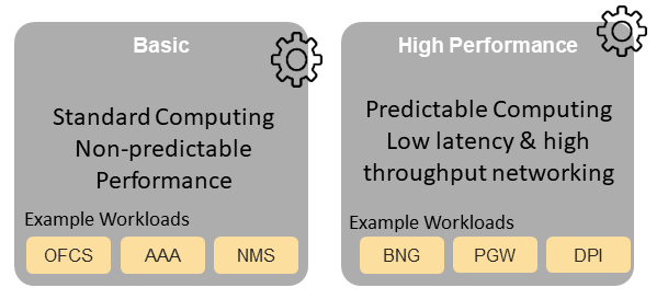
Figure 4.2 Cloud infrastructure profiles
The two Profiles, Profile Extensions & Flavours are as follows:
Basic (B): for Workloads that can tolerate resource over-subscription and variable latency.
High Performance (H): for Workloads that require predictable computing performance, high network throughput and low
network latency.
The availability of these two profiles facilitates and accelerates the workload deployment. The intent of the above profiles is to match the Cloud Infrastructure to the most common needs of the workloads, and to allow for a more comprehensive configuration using profile extensions when needed. These profiles are offered with extensions, that specify capability deviations and allow for the specification of more capabilities. The Cloud Infrastructure will have nodes configured as with options, such as virtual interface options, storage extensions, and acceleration extensions.
The justification for defining these two profiles, and a set of extensible profile extensions, is provided in the section Profiles, Profile Extensions & Flavours. It includes the following:
Workloads can be deployed by requesting compute hosts configured according to a specific profile (basic or high performance).
Profile extensions allow a more granular compute host configuration for the workload (such as GPU, high-speed network, and Edge deployment).
Cloud infrastructure “scattering” is minimised.
Workload development and testing optimisation by using predefined and commonly supported (Telco operators) profiles and extensions.
Better usage of cloud objects (memory, processor, network, and storage).
Workload flavours specify the resource sizing information including network and storage (size, throughput, and IOPS). Figure 4.3 shows three resources (VM or Pod) on nodes configured in accordance with the specified profile (‘B’ and ‘H’), and the resource sizes.
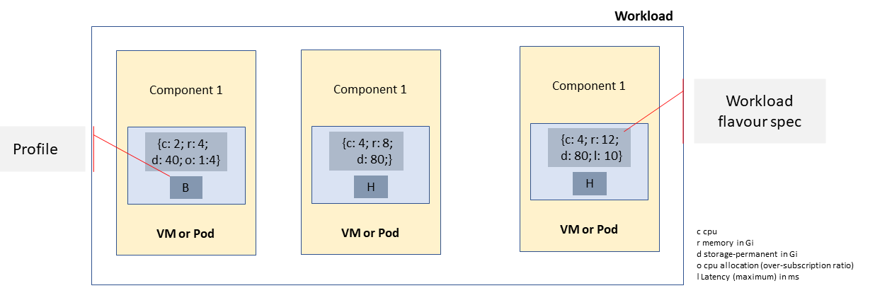
Figure 4.3 Workloads built against Cloud Infrastructure profiles and workload flavours
A node configuration can be specified using the following syntax:
<profile name>[.<profile_extension>][.<extra profile specs>]
In this syntax, the specifications enclosed within the square brackets ([ and ]) are optional. The ‘extra profile specs’ are needed to capture the special node configurations not accounted for by the profile and profile extensions.
Example node configurations can be as follows: B, B.low-latency, H, and H.very-high-speed-network.very-low-latency-edge.
A workload needs to specify the configuration and capabilities of the infrastructure that it can run on, the size of the resources it needs, and additional information (extra-specs), such as whether or not the workload can share core siblings (SMT thread), whether or not it has affinity (that is, it needs to be placed on the same infrastructure node) with other workloads, and so on. The capabilities required by the workload can therefore be specified using the following syntax:
<profile name>[.<profile_extension>][.<extra profile specs>].<workload flavour specs>[.<extra-specs>]
In this syntax, the <workload flavour specs> are specified as defined in section 4.2.4.3 Workload Flavours and Other Capabilities Specifications Format below.
4.2.1. Profiles
4.2.1.1. Basic profile
Hardware resources are configured in accordance with the Basic profile (B) in such a way that they are only suited for workloads that tolerate variable performance. This includes latency and resource oversubscription. Only Simultaneous Multi-Threading (SMT) is configured on nodes that support the Basic profile. With no NUMA alignment, the executing processes of the vCPUs may not be on the same NUMA node as the memory used by these processes. When the vCPU and memory are on different NUMA nodes, memory accesses are not local to the vCPU node and therefore add latency to memory accesses. The Basic profile supports oversubscription (using the CPU Allocation Ratio) which is specified as part of the sizing information in the workload profiles.
4.2.1.2. High-performance profile
The high-performance profile (H) is intended to be used for workloads that require predictable performance, high network throughput requirements, and/or low network latency. To satisfy predictable performance needs, NUMA alignment, CPU pinning, and huge pages are enabled. For obvious reasons, the high-performance profile does not support oversubscription.
4.2.2. Profiles specifications and capability mapping
Ref |
Capability |
Basic |
High performance |
Notes |
|---|---|---|---|---|
e.cap.006 |
CPU pinning |
No |
Yes |
Exposed performance capabilities according to Table 4-2. |
e.cap.007 |
NUMA alignment |
No |
Yes |
|
e.cap.013 |
SR-IOV over PCI-PT |
No |
Yes |
|
e.cap.018 |
Simultaneous Multithreading (SMT) |
Yes |
Optional |
|
e.cap.019 |
vSwitch optimisation (DPDK) |
No |
Yes |
DPDK does not have to be used if another network acceleration method is being utilised. |
e.cap.020 |
CPU Architecture |
<value> |
<value> |
Values, such as x64, ARM, and so on. |
e.cap.021 |
Host operating system (OS) |
<value> |
<value> |
Values, such as a specific Linux version, Windows version, and so on. |
e.cap.022 |
Virtualisation infrastructure Layer1 |
<value> |
<value> |
Values, such as KVM, Hyper-V, Kubernetes, and so on, when relevant, depending on technology. |
e.cap.023 |
Huge page support according to Table 4-7. |
No |
Yes |
Internal performance capabilities, according to Table 4-7. |
e.cap.025 |
AF_XDP |
No |
Optional |
These capabilities require workload support for the AF_XDP socket type. |
i.cap.019 |
CPU clock speed |
<value> |
<value> |
This capability specifies the Cloud Infrastructure CPU clock speed, in GHz. |
i.cap.020 |
Storage encryption |
Yes |
Yes |
This capability specifies whether or not the Cloud Infrastructure supports storage encryption. |
1 See Figure 5-1 Cloud Infrastructure Software profile description.
4.2.3. Profile extensions
Profile extensions represent small deviations from, or further qualification of, the profiles that do not require the partitioning of the infrastructure into separate pools, but which have specifications with a finer granularity of the profile. Profile Extensions provide workloads with a more granular control over what kind of infrastructure they can run on.
Profile Extension Name |
Mnemonic |
Applicable to the basic profile |
Applicable to the high performance profile |
Description |
Notes |
|---|---|---|---|---|---|
Compute-intensive high-performance CPU |
compute-high-perf-cpu |
❌ |
✅ |
Nodes that have predictable computing performance and higher clock speeds. |
May use vanilla VIM/K8S scheduling instead. |
Storage-intensive high-performance storage |
storage-high-perf |
❌ |
✅ |
Nodes that have low storage latency and/or high-storage IOPS. |
|
Compute-intensive high memory |
compute-high-memory |
❌ |
✅ |
Nodes that have high amounts of RAM. |
May use vanilla VIM/K8S scheduling instead. |
Compute-intensive GPU |
compute-gpu |
❌ |
✅ |
For compute-intensive workloads that require GPU compute resources on the node. |
May use node feature discovery. |
Network-intensive |
high-speed-network |
❌ |
✅ |
Nodes configured to support SR-IOV. |
|
Network-intensive high-speed network (25G) |
high-speed-network |
❌ |
✅ |
Denotes the presence of network links (to the DC network) of speeds of 25 Gbps or more on the node. |
|
Network-intensive high-speed speed network (100G) |
very-high-speed-network |
❌ |
✅ |
Denotes the presence of network links (to the DC network) of speeds of 100 Gbps or more on the node. |
|
Low latency - Edge sites |
low-latency-edge |
✅ |
✅ |
Labels a host or node as located in an Edge site, for workloads requiring low latency (specify value) to final users or geographical distribution. |
|
Very low latency - Edge sites |
very-low-latency-edge |
✅ |
✅ |
Labels a host or node as located in an Edge site, for workloads requiring low latency (specify value) to final users or geographical distribution. |
|
Ultra-low low latency - Edge sites |
ultra-low-latency-edge |
✅ |
✅ |
Labels a host or node as located in an Edge site, for workloads requiring low latency (specify value) to final users or geographical distribution. |
|
Fixed-function accelerator |
compute-ffa |
❌ |
✅ |
Labels a host or node that includes a consumable fixed-function accelerator (non-programmable, for example, Crypto, vRAN-specific adapter). |
|
Firmware-programmable adapter |
compute-firmware programmable |
❌ |
✅ |
Labels a host or node that includes a consumable firmware-programmable adapter (for example, Network/storage adapter). |
|
SmartNIC-enabled |
network-smartnic |
❌ |
✅ |
Labels a host or node that includes a programmable accelerator. |
|
SmartSwitch-enabled |
network-smartswitch |
❌ |
✅ |
Labels a host or node that is connected to a programmable switch fabric or a TOR switch. |
4.2.4. Workload flavours and specifications of other capabilities
The workload requests a set of resource capabilities, including its components, that it needs to run successfully. The GSMA document OPG.02 “Operator Platform: Requirements and Architecture” [24] defines “Resource Flavour” as this set of capabilities. A Resource Flavour specifies the resource profile, any profile extensions, and the size of the resources needed (workload flavour), as well as extra specifications for workload placement, as defined in Section 4.2 Profiles and Workload Flavours above.
This section provides details of the capabilities that need to be provided in a resource request. The profiles, the profile specifications, and the profile extensions specify the infrastructure (hardware and software) configuration. In a resource request, they need to be augmented with workload-specific capabilities and configurations, including the sizing of requested resource, extra specifications including those related to the placement of the workload section 4.2.4.2, virtual network section 4.2.5, and storage extensions section 4.2.6.
4.2.4.1. Geometry of workload flavours (Sizing)
Workload flavours (sometimes also referred to as “compute flavours”) are sizing specifications beyond the capabilities specified by the node profiles. Workload flavours represent the compute, memory, storage, and network resource sizing templates used in requesting resources on a host that is conformant with the profiles and profile extensions. The workload flavour specifies the compute, memory, and storage characteristics of the requested resource (VM, container). Workload Flavours can also specify different storage resources, such as ephemeral storage, swap disk, network speed, and storage IOPs.
Workload flavour sizing consists of the following:
Element |
Mnemonic |
Description |
|---|---|---|
cpu |
c |
Number of virtual compute resources (vCPUs). |
memory |
r |
Virtual resource instance memory, in megabytes. |
storage - ephemeral |
e |
Specifies the size of an ephemeral/local data disk that exists only for the life of the instance. The default value is 0. The ephemeral disk may be partitioned into boot (base image) and swap space disks. |
storage - persistent |
d |
Specifies the disk size of persistent storage. |
Table 4-12: Workload flavour geometry specification.
The flavours’ syntax consists of <element, value> pairs, separated by a colon (“:”), for example: {cpu: 4; memory: 8 Gi; storage-permanent: 80 Gi}.
4.2.4.2. Specifications of the extra capabilities of the workloads
Besides the sizing information, a workload may need to specify additional capabilities. These include capabilities for workload placement, such as latency, and workload affinity and non-affinity. They also include capabilities such as workload placement on multiple NUMA nodes. The extra specifications include the Virtual Network Interface Specifications and Storage Extensions.
Attribute |
Description |
|---|---|
CPU allocation ratio |
This attribute specifies the maximum CPU allocation (a.k.a. oversubscription) ratio supported by a workload. |
Compute-intensive |
This attribute is for demanding workloads with stringent memory access requirements, where the single NUMA bandwidth may be a limitation. The compute-intensive workload profile is used to enable the workload to be spread across all NUMA nodes. |
Latency |
This attribute specifies the latency requirements used for locating workloads. |
Affinity |
This attribute specifies the workloads that should be hosted on the same computer node. |
Non-affinity |
This attribute specifies workloads that should not be hosted on the same computer node. |
Dedicated cores |
This attribute specifies whether or not the workload can share sibling threads with other workloads. The default is No such that it allows different workloads on different threads. |
Network interface option |
See Section 4.2.5. |
Storage extension |
See Section 4.2.6. |
4.2.4.3. Format of the workload flavours and other capability specifications
The following table shows a complete list of the specifications that need to be specified by the workloads.
Profile extension name |
Mnemonic |
Applicable to the basic profile |
Applicable to the high performance profile |
Description |
Notes |
|---|---|---|---|---|---|
CPU |
c |
✅ |
✅ |
The number of virtual compute resources (vCPUs). |
Required |
memory |
r |
✅ |
✅ |
The virtual resource instance memory, in megabytes. |
Required |
storage - ephemeral |
e |
✅ |
✅ |
This profile extension specifies the size of an ephemeral/local data disk that exists only for the life of the instance. The default value is 0. The ephemeral disk may be partitioned into boot (base image) and swap space disks. |
Optional |
storage - persistent |
d |
✅ |
✅ |
This profile extension specifies the disk size of persistent storage. |
Required |
storage - root disk |
b |
✅ |
✅ |
This profile extension specifies the size of the root disk. |
Optional |
CPU Allocation Ratio |
o |
✅ |
❌ |
This profile extension specifies the CPU allocation (or oversubscription) ratio. It can only be specified for the basic profile. For workloads that utilise nodes configured according to the high-performance profile, the CPU allocation ratio is 1:1. |
Required for Basic profile |
Compute-intensive |
ci |
✅ |
❌ |
This profile applies to demanding workloads with stringent memory access requirements, where the single NUMA bandwidth maybe a bandwidth. The compute-intensive workload profile is used to enable the workload to be spread across all NUMA nodes. |
Optional |
Latency |
l |
✅ |
✅ |
This profile specifies the latency requirements used for locating workloads. |
Optional |
Affinity |
af |
✅ |
✅ |
This profile specifies the workloads that should be hosted on the same computer node. |
Optional |
Non-affinity |
naf |
✅ |
✅ |
This profile specifies the workloads that should not be hosted on the same computer node. |
Optional |
Dedicate cores |
dc |
✅ |
❌ |
This profile specifies whether or not the workload can share sibling threads with other workloads. The default value is No, thereby allowing different workloads on differnt threads. |
Optional |
Network interface option |
dc |
✅ |
✅ |
See below. |
Optional |
Storage extension |
s |
✅ |
✅ |
See below. |
Optional |
Profile name |
pn |
✅ |
✅ |
This profile specifies profile “B” or “H”. |
Required |
Profile extension |
pe |
❌ |
✅ |
This profile specifies the profile extensions. |
Optional |
Profile extra specs |
pes |
❌ |
✅ |
This profile specifies the special node configurations not accounted for by the profile and the profile extensions. |
Optional |
Table 4-13: Specifications of resource flavours (complete list of workload capabilities)
4.2.5. Virtual network interface specifications
The virtual network interface specifications extend a flavour customisation with network interfaces with an associated bandwidth. They are identified by the literal “n”, followed by the interface bandwidth, in Gbps. Multiple network interfaces can be specified by repeating the “n” option.
Virtual interfaces may be of an access type and therefore untagged, or of a trunk type, with one or more 802.1Q tagged logical interfaces. Tagged interfaces are encapsulated by the overlay, so that tenant isolation (that is, security) is maintained, irrespective of the tag values applied by the workload.
- Note: The number of virtual network interfaces, or vNICs, associated with a virtual compute instance, is directly
related to the number of vNIC extensions declared for the environment. The vNIC extension is not part of the base flavour.
<network interface bandwidth option> :: <”n”><number (bandwidth in Gbps)>
Virtual Network Interface Option |
Interface Bandwidth |
|---|---|
n1, n2, n3, n4, n5, n6 |
1, 2, 3, 4, 5, 6 Gbps |
n10, n20, n30, n40, n50, n60 |
10, 20, 30, 40, 50, 60 Gbps |
n25, n50, n75, n100, n125, n150 |
25, 50, 75, 100, 125, 150 Gbps |
n50, n100, n150, n200, n250, n300 |
50, 100, 150, 200, 250, 300 Gbps |
n100, n200, n300, n400, n500, n600 |
100, 200, 300, 400, 500, 600 Gbps |
Table 4-14: Virtual network interface specification examples
4.2.6. Storage extensions
Persistent storage is associated with workloads via storage extensions. The storage qualities specified by the Storage Extension pertain to the “Platform Native - Hypervisor Attached” and “Platform Native - Container Persistent” storage types, as defined in “3.6.3 Storage for Tenant Consumption”. The size of an extension can be specified explicitly in increments of 100 GB (Table 4-15), ranging from a minimum of 100 GB to a maximum of 16 TB. Extensions are configured with the required performance category, in accordance with Table 4-15. Multiple persistent storage extensions can be attached to virtual compute instances.
Note: This specification uses GB and GiB to refer to a Gibibyte (2^30 bytes), except where otherwise stated.
.conf |
Read IO/s |
Write IO/s |
Read throughput (MB/s) |
Write throughput (MB/s) |
Max. ext. size |
|---|---|---|---|---|---|
.bronze |
Up to 3K |
Up to 1.5K |
Up to 180 |
Up to 120 |
16TB |
.silver |
Up to 60K |
Up to 30K |
Up to 1200 |
Up to 400 |
1TB |
.gold |
Up to 680K |
Up to 360K |
Up to 2650 |
Up to 1400 |
1TB |
Table 4-15: Storage Extensions
Note: Performance is based on a block size of 256 KB or larger.