4 Infrastructure Capabilities, Measurements and Catalogue 
Table of Contents 
4.1 Capabilities and Performance Measurements 
This section describes and uniquely identifies the Capabilities provided directly by the Infrastructure, as well as Performance Measurements (PMs) generated directly by the Infrastructure (i.e. without the use of external instrumentation).
The Capability and PM identifiers conform to the following schema:
a.b.c
(Ex. “e.pm.001”)
a = Scope <(e)xternal | (i)nternal | (t)hird_party_instrumentation>
b = Type <(cap) capability | (man) management | (pm) performance | (man-pm)>
c = Serial Number
4.1.1 Exposed vs Internal 
The following pertains to the context of Cloud Infrastructure Resources, Capabilities and Performance Measurements (PMs) as discussed within this chapter.
Exposed: Refers to any object (e.g., resource discovery/configuration/consumption, platform telemetry, Interface, etc.) that exists in or pertains to, the domain of the Cloud Infrastructure and is made visible (aka “Exposed”) to a workload. When an object is exposed to a given workload, the scope of visibility within a given workload is at the discretion of the specific workload’s designer. From an Infra perspective, the Infra-resident object is simply being exposed to one or more virtual environments (i.e. Workloads). It is then the responsibility of the kernel or supervisor/executive within the VM to control how, when and where the object is further exposed within the VM, with regard to permissions, security, etc. As the object(s) originate with the Infra, they are by definition visible within that domain.
Internal: Effectively the opposite of Exposed; objects Internal to the Cloud Infrastructure, which are exclusively available for use by the Cloud Infrastructure and components within the Cloud Infrastructure.
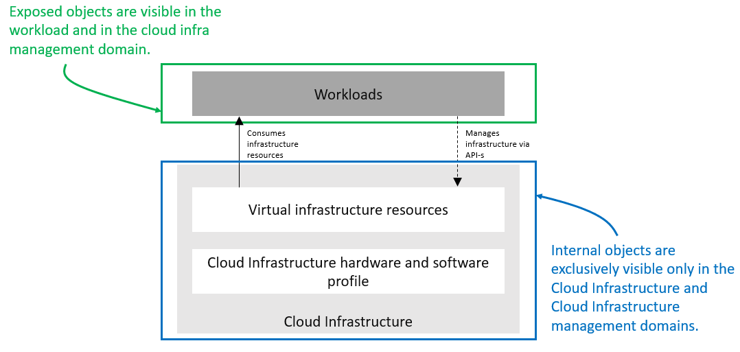
Figure 4-1: Exposed vs. Internal Scope
As illustrated in the figure above, objects designated as “Internal” are only visible within the area inside the blue oval (the Cloud Infrastructure), and only when the entity accessing the object has the appropriate permissions. Whereas objects designated as “Exposed” are potentially visible from both the area within the green oval (the Workload), as well as from within the Cloud Infrastructure, again provided the entity accessing the object has appropriate permissions.
Note: The figure above indicates the areas from where the objects are visible . It is not intended to indicate where the objects are instantiated . For example, the virtual resources are instantiated within the Cloud Infrastructure (the blue area), but are Exposed, and therefore are visible to the Workload, within the green area.
4.1.2 Exposed Infrastructure Capabilities 
This section describes a set of explicit Cloud Infrastructure capabilities and performance measurements that define a Cloud Infrastructure. These capabilities and PMs are well known to workloads as they provide capabilities which workloads rely on.
Note : It is expected that Cloud Infrastructure capabilities and measurements will expand over time as more capabilities are added and technology enhances and matures.
4.1.2.1 Exposed Resource Capabilities 
Table 4-1 below shows resource capabilities of Cloud Infrastructure. Those indicate resources offered to workloads by Cloud Infrastructure.
| Ref | Cloud Infrastructure Capability | Unit | Definition/Notes |
|---|---|---|---|
| e.cap.001 | # vCPU | number | Max number of vCPUs that can be assigned to a single VM or Pod 1) |
| e.cap.002 | RAM Size | MB | Max memory in MB that can be assigned to a single VM or Pod by the Cloud Infrastructure 2) |
| e.cap.003 | Total per-instance (ephemeral) storage | GB | Max storage in GB that can be assigned to a single VM or Pod by the Cloud Infrastructure |
| e.cap.004 | # Connection points | number | Max number of connection points that can be assigned to a single VM or Pod by the Cloud Infrastructure |
| e.cap.005 | Total external (persistent) storage | GB | Max storage in GB that can be attached / mounted to VM or Pod by the Cloud Infrastructure |
Table 4-1: Exposed Resource Capabilities of Cloud Infrastructure
1)
In a Kubernetes based environment this means the CPU limit of a pod.
2)
In a Kubernetes based environment this means the memory limit of a pod.
4.1.2.2 Exposed Performance Optimisation Capabilities 
Table 4-2 shows possible performance optimisation capabilities that can be provided by Cloud Infrastructure. These indicate capabilities exposed to workloads. These capabilities are to be consumed by workloads in a standard way.
| Ref | Cloud Infrastructure Capability | Unit | Definition/Notes |
|---|---|---|---|
| e.cap.006 | CPU pinning | Yes/No | Indicates if Cloud Infrastructure supports CPU pinning |
| e.cap.007 | NUMA alignment | Yes/No | Indicates if Cloud Infrastructure supports NUMA alignment |
| e.cap.008 | IPSec Acceleration | Yes/No | IPSec Acceleration |
| e.cap.009 | Crypto Acceleration | Yes/No | Crypto Acceleration |
| e.cap.010 | Transcoding Acceleration | Yes/No | Transcoding Acceleration |
| e.cap.011 | Programmable Acceleration | Yes/No | Programmable Acceleration |
| e.cap.012 | Enhanced Cache Management | Yes/No | If supported, L=Lean; E=Equal; X=eXpanded. L and X cache policies require CPU pinning to be active. |
| e.cap.013 | SR-IOV over PCI-PT | Yes/No | Traditional SR-IOV. These Capabilities generally require hardware-dependent drivers be injected into workloads. As such, use of these features shall be governed by the applicable CNTT policy. Consult the relevant RA specification for the usage policy relevant to any needed hardware capability of this type. |
| e.cap.014 | GPU/NPU | Yes/No | Hardware coprocessor. These Capabilities generally require hardware-dependent drivers be injected into workloads. As such, use of these features shall be governed by the applicable CNTT policy. Consult the relevant RA specification for the usage policy relevant to any needed hardware capability of this type. |
| e.cap.015 | SmartNIC | Yes/No | Network Acceleration. SmartNICs that do not utilise PCI-PT are not subject to the CNTT principles, nor any related policies or prohibitions. |
| e.cap.016 | FPGA/other Acceleration H/W | Yes/No | Non-specific hardware. These Capabilities generally require hardware-dependent drivers be injected into workloads. As such, use of these features shall be governed by the applicable CNTT policy. Consult the relevant RA specification for the usage policy relevant to any needed hardware capability of this type. |
Table 4-2: Exposed Performance Optimisation Capabilities of Cloud Infrastructure
Enhanced Cache Management is a compute performance enhancer that applies a cache management policy to the socket hosting a given virtual compute instance, provided the associated physical CPU microarchitecture supports it. Cache management policy can be used to specify the static allocation of cache resources to cores within a socket. The “Equal” policy distributes the available cache resources equally across all of the physical cores in the socket. The “eXpanded” policy provides additional resources to the core pinned to a workload that has the “X” attribute applied. The “Lean” attribute can be applied to workloads which do not realize significant benefit from a marginal cache size increase and are hence willing to relinquish unneeded resources.
In addition to static allocation, an advanced Reference Architecture implementation can implement dynamic cache management control policies, operating with tight (~ms) or standard (10s of seconds) control loop response times, thereby achieving higher overall performance for the socket.
4.1.2.3 Exposed Monitoring Capabilities 
Monitoring capabilities are used for the passive observation of workload-specific traffic traversing the Cloud Infrastructure. As with all capabilities, Monitoring may be unavailable or intentionally disabled for security reasons in a given Cloud Infrastructure deployment. If this functionality is enabled, it must be subject to strict security policies. Refer to the Reference Model Security chapter for additional details.
Table 4-3 shows possible monitoring capabilities available from the Cloud Infrastructure for workloads.
| Ref | Cloud Infrastructure Capability | Unit | Definition/Notes |
|---|---|---|---|
| e.cap.017 | Monitoring of L2-7 data | Yes/No | Ability to monitor L2-L7 data from workload |
Table 4-3: Exposed Monitoring Capabilities of Cloud Infrastructure
4.1.3 Exposed Infrastructure Performance Measurements 
The intent of the following PMs is to be available for and well known to workloads.
4.1.3.1 Exposed Performance Measurements 
The following table of exposed Performance Measurements shows PMs per VM or Pod, vNIC or vCPU. Network test setups are aligned with ETSI GS NFV-TST 009 [14]. Specifically exposed PMs use a single workload (PVP) dataplane test setup in a single host.
| Ref | Cloud Infrastructure Measurement | Unit | Definition/Notes |
|---|---|---|---|
| e.pm.xxx | Place Holder | Units | Concise description |
Table 4-4: Exposed Performance Measurements of Cloud Infrastructure
4.1.4 Internal Infrastructure Capabilities 
This section covers a list of implicit Cloud Infrastructure capabilities and measurements that define a Cloud Infrastructure. These capabilities and metrics determine how the Cloud Infrastructure behaves internally. They are hidden from workloads (i.e. workloads may not know about them) but they will impact the overall performance and capabilities of a given Cloud Infrastructure solution.
Note : It is expected that implicit Cloud Infrastructure capabilities and metrics will evolve with time as more capabilities are added as technology enhances and matures.
4.1.4.1 Internal Resource Capabilities 
Table 4-5 shows resource capabilities of Cloud Infrastructure. These include capabilities offered to workloads and resources consumed internally by Cloud Infrastructure.
| Ref | Cloud Infrastructure Capability | Unit | Definition/Notes |
|---|---|---|---|
| i.cap.014 | CPU cores consumed by the Cloud Infrastructure overhead on a worker (compute) node | % | The ratio of cores consumed by the Cloud Infrastructure components (including host OS) in a compute node to the total number of cores available expressed as a percentage |
| i.cap.015 | Memory consumed by the Cloud Infrastructure overhead on a worker (compute) node | % | The ratio of memory consumed by the Cloud Infrastructure components (including host OS) in a worker (compute) node to the total available memory expressed as a percentage |
Table 4-5: Internal Resource Capabilities of Cloud Infrastructure
4.1.4.2 Internal SLA capabilities 
Table 4-6 below shows SLA (Service Level Agreement) capabilities of Cloud Infrastructure. These include Cloud Infrastructure capabilities required by workloads as well as required internal to Cloud Infrastructure. Application of these capabilities to a given workload is determined by its Cloud Infrastructure Profile.
| Ref | Cloud Infrastructure capability | Unit | Definition/Notes |
|---|---|---|---|
| i.cap.016 | CPU allocation ratio | N:1 | Number of virtual cores per physical core; also known as CPU overbooking ratio |
| i.cap.017 | Connection point QoS | Yes/No | QoS enablement of the connection point (vNIC or interface) |
Table 4-6: Internal SLA capabilities to Cloud Infrastructure
4.1.4.3 Internal Performance Optimisation Capabilities 
Table 4-7 below shows possible performance optimisation capabilities that can be provided by Cloud Infrastructure. These include capabilities exposed to workloads as well as internal capabilities to Cloud Infrastructure. These capabilities will be determined by the Cloud Infrastructure Profile used by the Cloud Infrastructure.
| Ref | Cloud Infrastructure capability | Unit | Definition/Notes |
|---|---|---|---|
| i.cap.018 | Huge pages | Yes/No | Indicates if the Cloud Infrastructure supports huge pages |
Table 4-7: Internal performance optimisation capabilities of Cloud Infrastructure
4.1.4.4 Internal Performance Measurement Capabilities 
Table 4-8 shows possible performance measurement capabilities available by Cloud Infrastructure. The availability of these capabilities will be determined by the Cloud Infrastructure Profile used by the workloads.
| Ref | Cloud Infrastructure Measurement | Unit | Definition/Notes |
|---|---|---|---|
| i.pm.001 | Host CPU usage | nanoseconds | Per Compute node. It maps to ETSI GS NFV-TST 008 V3.2.1 [5] clause 6, processor usage metric (Cloud Infrastructure internal). |
| i.pm.002 | Virtual compute resource (vCPU) usage | nanoseconds | Per VM or Pod. It maps to ETSI GS NFV-IFA 027 v2.4.1 [6] Mean vCPU usage and Peak vCPU usage (Cloud Infrastructure external). |
| i.pm.003 | Host CPU utilization | % | Per Compute node. It maps to ETSI GS NFV-TST 008 V3.2.1 [5] clause 6, processor usage metric (Cloud Infrastructure internal). |
| i.pm.004 | Virtual compute resource (vCPU) utilization | % | Per VM or Pod. It maps to ETSI GS NFV-IFA 027 v2.4.1 [6] Mean vCPU usage and Peak vCPU usage (Cloud Infrastructure external). |
| i.pm.005 | Measurement of external storage IOPS | Yes/No | |
| i.pm.006 | Measurement of external storage throughput | Yes/No | |
| i.pm.007 | Available external storage capacity | Yes/No |
Table 4-8: Internal Measurement Capabilities of Cloud Infrastructure
4.1.5 Cloud Infrastructure Management Capabilities 
The Cloud Infrastructure Manager (CIM) is responsible for controlling and managing the Cloud Infrastructure compute, storage, and network resources. Resources allocation is dynamically set up upon workloads requirements. This section covers the list of capabilities offered by the CIM to workloads or service orchestrator.
Table 4-9 shows capabilities related to resources allocation.
| Ref | Cloud Infrastructure Management Capability | Unit | Definition/Notes |
|---|---|---|---|
| e.man.001 | Virtual Compute allocation | Yes/No | Capability to allocate virtual compute resources to a workload |
| e.man.002 | Virtual Storage allocation | Yes/No | Capability to allocate virtual storage resources to a workload |
| e.man.003 | Virtual Networking resources allocation | Yes/No | Capability to allocate virtual networking resources to a workload |
| e.man.004 | Multi-tenant isolation | Yes/No | Capability to isolate resources between tenants |
| e.man.005 | Images management | Yes/No | Capability to manage workload software images |
| e.man.010 | Compute Availability Zones | list of strings | The names of each Compute Availability Zone that was defined to separate failure domains |
| e.man.011 | Storage Availability Zones | list of strings | The names of each Storage Availability Zone that was defined to separate failure domains |
Table 4-9: Cloud Infrastructure Management Resource Allocation Capabilities
4.1.6 Cloud Infrastructure Management Performance Measurements 
Table 4-10 shows performance measurement capabilities.
| Ref | Cloud Infrastructure Management Capability | Unit | Definition/Notes |
|---|---|---|---|
| e.man.006 | Virtual resources inventory per tenant | Yes/No | Capability to provide information related to allocated virtualised resources per tenant |
| e.man.007 | Resources Monitoring | Yes/No | Capability to notify state changes of allocated resources |
| e.man.008 | Virtual resources Performance | Yes/No | Capability to collect and expose performance information on virtualised resources allocated |
| e.man.009 | Virtual resources Fault information | Yes/No | Capability to collect and notify fault information on virtualised resources |
Table 4-10: Cloud Infrastructure Management Performance Measurement Capabilities
4.1.6.1 Resources Management Measurements 
Table 4-11 shows resource management measurements of CIM as aligned with ETSI GR NFV IFA-012 [15]. The intention of this table is to provide a list of measurements to be used in the Reference Architecture specifications, where the concrete values allowed for these measurements in the context of a particular Reference Architecture will be defined.
| Ref | Cloud Infrastructure Management Measurement | Unit | Definition/Notes |
|---|---|---|---|
| e.man-pm.001 | Time to create Virtual Compute resources (VM/container) for a given workload | Max ms | |
| e.man-pm.002 | Time to delete Virtual Compute resources (VM/container) of a given workload | Max ms | |
| e.man-pm.003 | Time to start Virtual Compute resources (VM/container) of a given workload | Max ms | |
| e.man-pm.004 | Time to stop Virtual Compute resources (VM/container) of a given workload | Max ms | |
| e.man-pm.005 | Time to pause Virtual Compute resources (VM/container) of a given workload | Max ms | |
| e.man-pm.006 | Time to create internal virtual network | Max ms | |
| e.man-pm.007 | Time to delete internal virtual network | Max ms | |
| e.man-pm.008 | Time to update internal virtual network | Max ms | |
| e.man-pm.009 | Time to create external virtual network | Max ms | |
| e.man-pm.010 | Time to delete external virtual network | Max ms | |
| e.man-pm.011 | Time to update external virtual network | Max ms | |
| e.man-pm.012 | Time to create external storage ready for use by workload | Max ms |
Table 4-11: Cloud Infrastructure management Resource Management Measurements
4.2 Infrastructure Profiles Catalogue 
Infrastructure exposes compute Flavours with options, virtual interface options, storage extensions, and acceleration extensions to workloads. These Cloud Infrastructure Profiles are offered to workloads with their corresponding options and extensions.
The idea of the Cloud Infrastructure profiles is to have a predefined set of infrastructure capabilities with a predefined set of compute Flavours which workload vendors use to build their workloads. Each workload can use several Flavours from different Cloud Infrastructure Profiles to build its overall functionality as illustrated in Figure 4-2 .
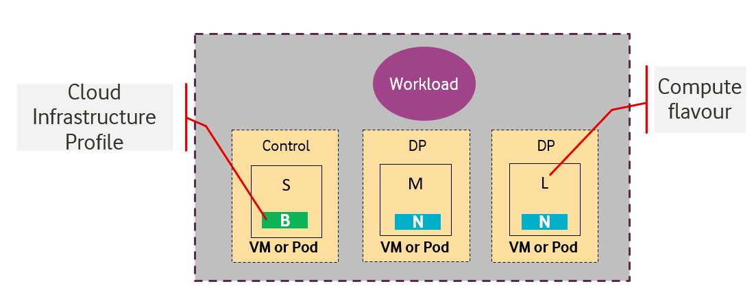
Figure 4-2: Workloads built against Cloud Infrastructure Profiles and compute Flavours.
4.2.1 Compute Flavours 
Compute Flavours represent the compute, memory, storage, and management network resource templates that are used by VMs on the compute hosts. Each VM is given a compute Flavour (resource template), which determines the VMs compute, memory and storage characteristics.
Compute Flavours can also specify secondary ephemeral storage, swap disk, etc. A compute Flavour geometry consists of the following elements:
| Element | Description |
|---|---|
| Compute Flavour Name | A descriptive name |
| Number of vCPUs | Number of virtual compute resources (vCPUs) presented to the VM instance. |
| Memory | Virtual compute instance memory in megabytes. |
| Ephemeral/Local Disk |
Specifies the size of an ephemeral data disk that exists only for the life of the instance. Default value is 0.
The ephemeral disk may be partitioned into boot (base image) and swap space disks. |
| Management Interface | Specifies the bandwidth of management interface/s |
Table 4-12: Compute Flavour Geometry Specification.
4.2.1.1 Predefined Compute Flavours 
The intent of the following Flavours list is to be comprehensive and yet effective to cover both IT and NFV workloads. The compute Flavours are specified relative to the “large” Flavour. The “large” Flavour configuration consists of 4 vCPUs, 8 GB of RAM and 80 GB of local disk, and the resulting virtual compute instance will have a management interface of 1 Gbps. The “medium” Flavour is half the size of a large and small is half the size of medium. The tiny Flavour is a special sized Flavour.
Note: Customised (Parameterized) Flavours can be used in concession by operators and, if needed, are created using TOSCA, HEAT templates, and/or VIM APIs.
| .conf | vCPU ("c") 2) | RAM ("r") 2) | Local Disk ("d") 3) | Bandwidth |
|---|---|---|---|---|
| .tiny | 1 | 512 MB | 1 GB | 1 Gbps |
| .small | 1 | 2 GB | 20 GB | 1 Gbps |
| .medium | 2 | 4 GB | 40 GB | 1 Gbps |
| .large | 4 | 8 GB | 80 GB | 1 Gbps |
| .2xlarge 1) | 8 | 16 GB | 160 GB | 1 Gbps |
| .4xlarge 1) | 16 | 32 GB | 320 GB | 1 Gbps |
| .8xlarge 1) | 32 | 64 GB | 640 GB | 1 Gbps |
Table 4-13: Predefined Compute Flavours.
1)
These compute Flavours are intended to be used for transitional purposes and workload vendors are expected to consume smaller Flavours and adopt microservices-based designs for their workloads.
2)
In Kubernetes based environments these are the resource requests of the containers in the pods. To get guaranteed resources the resource requests should be set to the same values as the resource limits, to get burstable resources the resource limits should be higher than the resource requests while to get best effort resources none of resource requests of resource limits should be set.
3)
The “local disk” is an ephemeral disk that provides storage for the life of a VM/Pod, and can either be provided by storage devices housed within the physical server on which the VM/Pod is running, or from an external storage device such as SAN or NFS.
4.2.2 Virtual Network Interface Specifications 
The virtual network interface specifications extend a Flavour customization with network interface(s), with an associated bandwidth, and are identified by the literal, “n”, followed by the interface bandwidth (in Gbps). Multiple network interfaces can be specified by repeating the “n” option.
Virtual interfaces may be of an Access type, and thereby untagged, or may be of a Trunk type, with one or more 802.1Q tagged logical interfaces. Note, tagged interfaces are encapsulated by the Overlay, such that tenant isolation (i.e. security) is maintained, irrespective of the tag value(s) applied by the workload.
Note, the number of virtual network interfaces, aka vNICs, associated with a virtual compute instance, is directly related to the number of vNIC extensions declared for the environment. The vNIC extension is not part of the base Flavour.
<network interface bandwidth option> :: <”n”><number (bandwidth in Gbps)>
| Virtual Network Interface Option | Interface Bandwidth |
|---|---|
| n1, n2, n3, n4, n5, n6 | 1, 2, 3, 4, 5, 6 Gbps |
| n10, n20, n30, n40, n50, n60 | 10, 20, 30, 40, 50, 60 Gbps |
| n25, n50, n75, n100, n125, n150 | 25, 50, 75, 100, 125, 150 Gbps |
| n50, n100, n150, n200, n250, n300 | 50, 100, 150, 200, 250, 300 Gbps |
| n100, n200, n300, n400, n500, n600 | 100, 200, 300, 400, 500, 600 Gbps |
Table 4-14: Virtual Network Interface Specification Examples
4.2.3 Storage Extensions 
Persistent storage is associated with workloads via Storage Extensions. The size of an extension can be specified explicitly in increments of 100GB, ranging from a minimum of 100GB to a maximum of 16TB. Extensions are configured with the required performance category, as per Table 4-15. Multiple persistent Storage Extensions can be attached to virtual compute instances.
Note: CNTT documentation uses GB and GiB to refer to a Gibibyte (2 30 bytes), except where explicitly stated otherwise.
| .conf | Read IO/s | Write IO/s | Read Throughput (MB/s) | Write Throughput (MB/s) | Max Ext Size |
|---|---|---|---|---|---|
| .bronze | Up to 3K | Up to 1.5K | Up to 180 | Up to 120 | 16TB |
| .silver | Up to 60K | Up to 30K | Up to 1200 | Up to 400 | 1TB |
| .gold | Up to 680K | Up to 360K | Up to 2650 | Up to 1400 | 1TB |
Table 4-15: Storage Extensions
Note: Performance is based on a block size of 256KB or larger.
4.2.4 Cloud Infrastructure Profiles 
4.2.4.1 Basic Profile 
This Cloud Infrastructure Profile is intended to be used for both IT workloads as well as NFV workloads. It has limited IO capabilities (up to 10Gbps Network interface).
4.2.4.2 Network Intensive Profile 
This Cloud Infrastructure Profile is intended to be used for those applications that has high network throughput requirements (up to 50Gbps).
4.2.4.2.1 Network Acceleration Extensions 
Network Intensive Profile can come with Network Acceleration extensions to assist workloads offloading some of their network intensive operations to hardware. The list below is preliminary and is expected to grow as more network acceleration resources are developed and standardized.
Note: Interface types are aligned with ETSI GS NFV-IFA 002 [7].
| .conf | Interface type | Description |
|---|---|---|
| .il-ipsec | virtio-ipsec | In-line IPSec acceleration. |
| .la-crypto | virtio-crypto | Look-Aside encryption/decryption engine. |
Table 4-16: Acceleration Extensions for Network Intensive Profile
Note: Need to work with relevant open source communities to create missing interfaces.
4.2.5 Cloud Infrastructure Profile Capabilities Mapping 
| Ref | Basic | Network Intensive | Notes |
|---|---|---|---|
e.cap.001
(#vCPU cores) |
Per selected \
|
Per selected \
|
Exposed resource capabilities as per Table 4-1 |
e.cap.002
(RAM Size (MB)) |
Per selected \
|
Per selected \
|
|
e.cap.003
(Total instance (ephemeral) storage (GB)) |
Per selected \
|
Per selected \
|
|
e.cap.004
(# Connection points) |
Per selected | Per selected | |
e.cap.005
(Total external (persistent) storage (GB)) |
Per selected
|
Per selected
|
|
e.cap.006
(CPU pinning) |
No | Yes | Exposed performance capabilities as per Table 4-2 |
e.cap.007
(NUMA alignment) |
No | Yes | |
e.cap.008
(IPSec Acceleration) |
No | Yes (if offered) | |
e.cap.009
(Crypto Acceleration) |
No | Yes (if offered) | |
e.cap.010
(Transcoding Acceleration) |
No | No | |
e.cap.011
(Programmable Acceleration) |
No | Yes/No | |
e.cap.012
(Enhanced Cache Management) |
E | E | |
e.cap.013
(SR-IOV over PCI-PT) |
No | Yes | |
e.cap.014
(GPU/NPU) |
No | Yes / No | Yes : in case of AI and Video Edge use cases |
e.cap.015
(SmartNIC) |
No | Yes / No | |
e.cap.016
(FPGA/other Acceleration H/W) |
No | Yes / No | Yes : in case of vRAN Edge use case |
i.cap.014
(CPU cores consumed by the Cloud Infrastructure on the worker nodes) |
any | any | |
i.cap.015
(Memory consumed by Cloud Infrastructure on the worker nodes) |
any | any | |
i.cap.016
(CPU allocation ratio) |
1:1 | 1:1 |
Internal SLA capabilities as per
Table 4-6
.
Note : This is set to 1:1 for the Basic profile to enable predictable and consistent performance during benchmarking and certification. Operators may choose to modify this for actual deployments if they are willing to accept the risk of performance impact to workloads using the basic profile. |
i.cap.017
(Connection point QoS) |
No | Yes | |
i.cap.018
(Huge page support) |
No | Yes | Internal performance capabilities as per Table 4-7 |
i.pm.001
(Host CPU usage) |
Yes | Yes | Internal monitoring capabilities as per Table 4-8 |
i.pm.002
(Virtual compute resource (vCPU) usage) |
Yes | Yes | |
i.pm.003
(Host CPU utilization) |
Yes | Yes | |
i.pm.004
(Virtual compute resource (vCPU) utilization) |
Yes | Yes | |
i.pm.005
(Measurement of external storage IOPS) |
Yes | Yes | |
i.pm.006
(Measurement of external storage throughput) |
Yes | Yes | |
i.pm.007
(Available external storage capacity) |
Yes | Yes |
Table 4-17: Mapping of Capabilities to Cloud Infrastructure Profiles
4.2.7 One stop shop 
4.2.7.1 Naming convention 
An entry in the infrastructure profile catalogue can be referenced using the following naming convention.
               B/N


               <I


               opt>


               .


               <Flavour>


               .


               <S


               ext>


               .


               <A


               ext>
Whereas:
- B/N : specifies the Cloud Infrastructure Profile (Basic or Network Intensive)
- <I opt> : specifies the interface option.
- <Flavour> : specifies the compute Flavour.
- <S ext> : specifies an optional storage extension.
- <A ext> : specifies an optional acceleration extension for the Network Intensive Cloud Infrastructure Profile.
Figure 4-3: Infrastructure Profiles Catalogue
4.2.7.2 Backwards Compatibility 
The Reference Model (RM) specification describes an infrastructure abstraction including a set of cloud infrastructure hardware and software profiles and compute flavours offered to workloads. The set of defined profiles and flavours will evolve along the releases but at the same time the existing workloads need to be supported. This means that any CNTT deployed cloud should be backwards compatible and support profiles and flavours from the latest three CNTT releases (N-2, N-1, N) as presented in Figure 4-4.
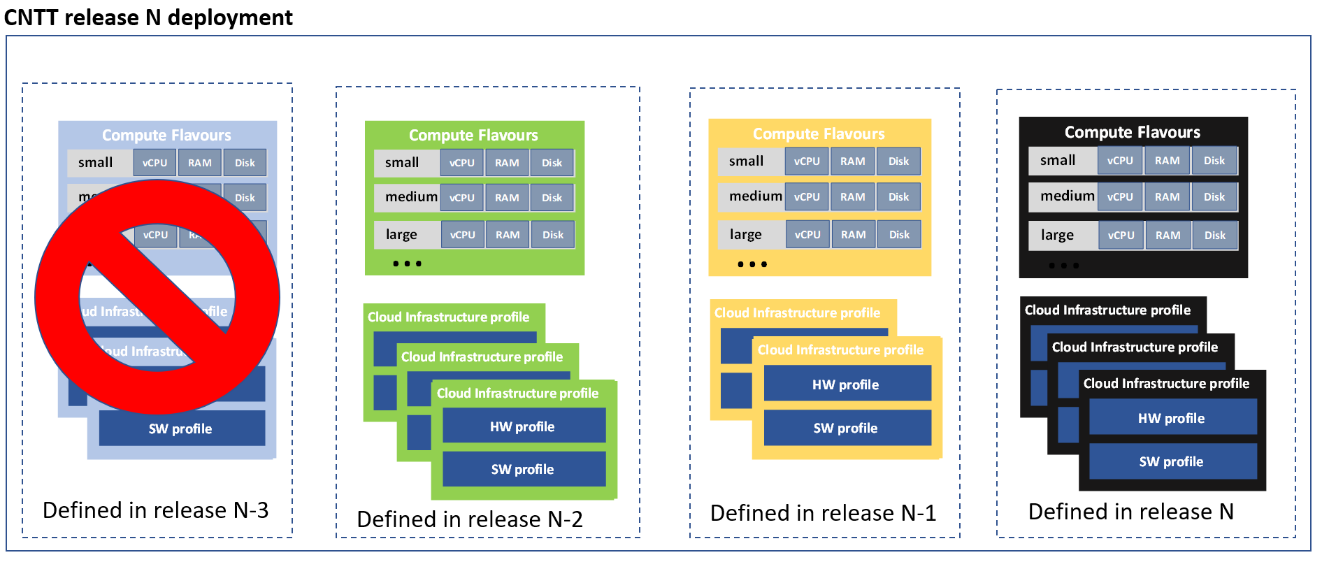
Figure 4-4: Backwards Compatibility
Cloud Infrastructure profiles that are available in CNTT release N deployment can be divided into two categories:
-
Cloud infrastructure profiles that are part of CNTT release N. These can be either
- new profiles defined in release N or
- existing profiles from earlier releases that are incorporated for backward compatibility reasons in release N
- Cloud infrastructure profiles from releases N-1 and N-2 that are deployed only because of backwards compatibility, these profiles are not part of CNTT release N definition.
Note: a profile defined in previous releases that is modified in release N is considered to be a new profile
Different profile categories described above are presented in Figure 4-5. In this example profiles that are part of CNTT release N consist of two new profiles (yellow), one profile that is originally defined in release N-1 (green) and one defined in release N-2 (blue). Profiles that were defined in earlier releases but are also supported in release N will be referred to by several names. Existing workloads continue using the profile names from previous releases. New workloads will use release N naming.
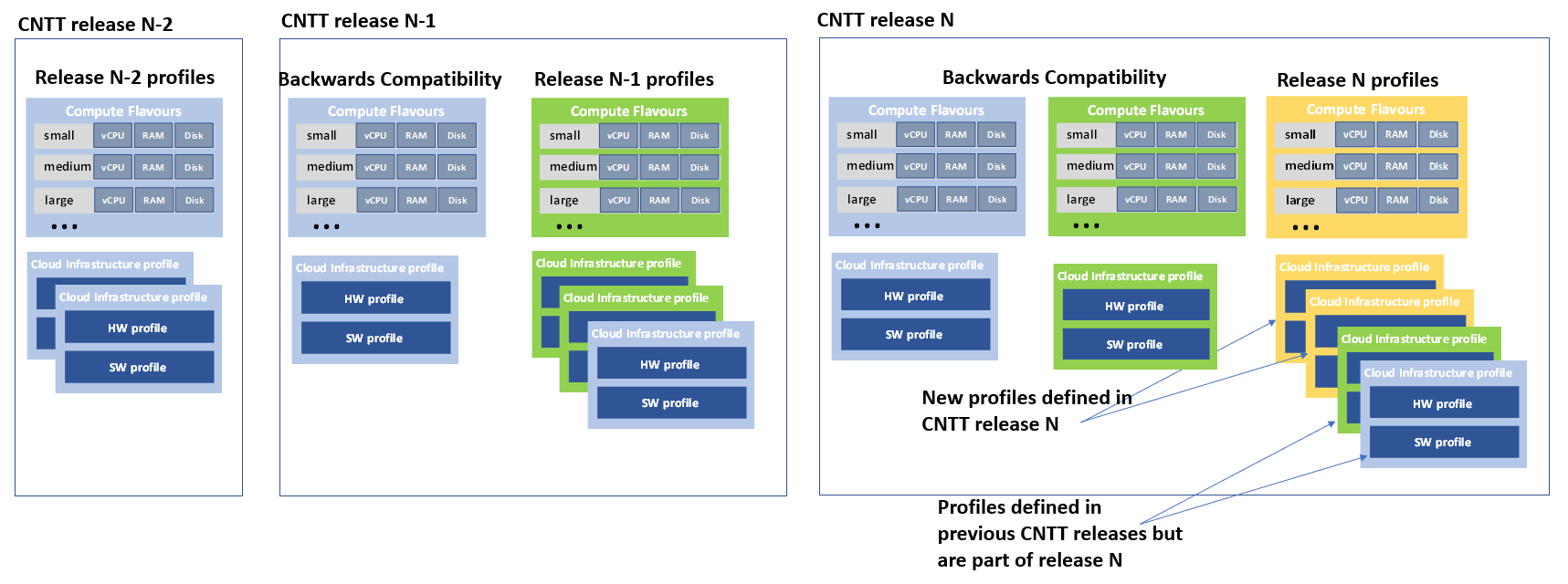
Figure 4-5: Cloud Infrastructure profiles in CNTT release N
Like predefined cloud infrastructure profiles, predefined compute flavours are also specified per CNTT release. CNTT release N flavours are used when new workloads are deployed into profiles that are part of the CNTT N release. Existing workloads continue using the flavours from previous releases. The difference in flavours can be for example, that newer flavours defined in release N may not have extra-large flavours that are earlier defined for transitional purposes. Workloads that use backwards compatible profiles will use the flavours from the older release (Figure 4-6).
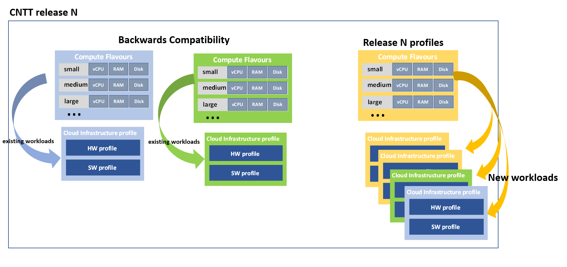
Figure 4-6: New workloads in Release N would use only Release N profiles
As discussed above backwards compatibility is the reason why cloud infrastructure profiles and flavours from several CNTT releases are configured and used in one CNTT deployment. Therefore, CNTT release number need to be added to each profile:
               B/N<”_Gen”><release


               #>.


               <Flavour>
Flavours are unique only when combined with a profile. For example, CNTT release N small flavour in basic profile has the naming:
B_GenN.small
4.2.7.3 Forward compatibility 
Technology specific exceptions are dealt with in the relevant RA specifications. Such exceptions are not part of any Cloud Infrastructure profile defined in CNTT.
4.3 Networking 
The Cloud Infrastructure Networking Reference Model is an essential foundation that governs all Reference Architectures and Cloud Infrastructure implementations to enable multiple cloud infrastructure virtualisation technology choices and their evolution. These include:
- the current single Infrastructure as a Service (IaaS) based virtualisation instances with Virtual Machines (VM)
- multi IaaS based virtualisation instances
- Cloud Native Container as a Service (CaaS) based virtualisation instances, and
- hybrid multi IaaS and CaaS based virtualisation instances
To retain the cloud paradigms of automation, scalability and usage of shared hardware resources when introducing CaaS instances it is necessary to enable an ability to co-deploy multiple simultaneous IaaS and CaaS instances on a shared pool of hardware resources.
Compute and Storage resources are rarely shared in between IaaS or CaaS instances, but the underpinning networking, most commonly implemented with Ethernet and IP, must be shared and managed as a shared pool of underlay network resources to enable the pooled usage of Compute and Storage from a managed shared pool.
Throughout this chapter and its figures a number of references to ETSI NFV are made and they explicitly are made towards the ETSI NFV models in the Architectural Framework:
- ETSI GS NFV 002 V1.2.1 [3]
- ETSI GR NFV-IFA 029 V3.3.1 [4]
4.3.1 Network Layering and Concepts 
Cloud and Telco networking are layered, and it is very important to keep the dependencies between the layers low to enable security, separation and portability in between multiple implementations and generations.
Before we start developing a deep model we need to agree on some foundational concepts and layering that allow decoupling of implementations in between the layers. We will emphasize four concepts in this section:
- Underlay and Overlay Networking concepts
- Hardware and Virtual Infrastructure Layer concepts
- Software Defined Underlay and Overlay Networking concepts
- Programmable Networking Fabric concept
4.3.1.1 Underlay and Overlay Networking concepts 
The ETSI Network Functions Virtualisation Architectural Framework (as referred above) describes how a Virtualization Layer instance abstract the hardware resources and separate Virtualisation Tenants (Workload) from each other. It does also specifically state that the control and implementation of the hardware layer is out of scope for that specification.
When having multiple Virtualization Layer instances on a shared hardware infrastructure, the networking can be layered in an Underlay and an Overlay Network layer. The purpose with this layering is to ensure separation of the Virtualisation Tenants (Workload) Overlay Networks from each other, whilst allowing the traffic to flow on the shared Underlay Network in between all Ethernet connected hardware (HW) devices.
The Overlay Networking separation is often done through encapsulation of Tenants traffic using overlay protocols e.g. through VxLAN or EVPN on the Underlay Networks e.g. based on L2 (VLAN) or L3 (IP) networks.
The Overlay Network for each Cloud Infrastructure deployment must support a basic primary Tenant Network between the Instances within each Tenant. Due to the nature of Telecom applications handling of Networks and their related Network Functions they often need access to external non-translated traffic flows and have multiple separated or secondary traffic channels with abilities for different traffic treatments.
In some instances, the Virtualisation Tenants can bypass the Overlay Networking encapsulation to achieve better performance or network visibility/control. A common method to bypass the Overlay Networking encapsulation normally done by the Virtualisation Layer, is the VNF/CNF usage of SR-IOV that effectively take over the Physical and Virtual Functions of the NIC directly into the VNF/CNF Tenant. In these cases, the Underlay Networking must handle the separation e.g. through a Virtual Termination End Point (VTEP) that encapsulate the Overlay Network traffic.
Note: Bypassing the Overlay Networking layer is a violation of the basic CNTT decoupling principles, but in some cases unavoidable with existing technologies and available standards. Until suitable technologies and standards are developed, CNTT have a set of agreed exemptions that forces the Underlay Networking to handle the bypassed Overlay Networking separation.
VTEP could be manually provisioned in the Underlay Networking or be automated and controlled through a Software Defined Networking controller interfaces into the underlying networking in the HW Infrastructure Layer.
4.3.1.2 Hardware and Virtual Infrastructure Layer concepts 
The Cloud Infrastructure (based on ETSI NFV Infrastructure with hardware extensions) can be considered to be composed of two distinct layers, here referred to as HW Infrastructure Layer and Virtual Infrastructure Layer. When there are multiple separated simultaneously deployed Virtual Infrastructure domains, the architecture and deployed implementations must enable each of them to be in individual non-dependent administrative domains. The HW Infrastructure must then also be enabled to be a fully separated administrative domain from all of the Virtualisation domains.
For Cloud Infrastructure implementations of multiple well separated simultaneous Virtual Infrastructure Layer instances on a shared HW Infrastructure there must be a separation of the hardware resources i.e. servers, storage and the Underlay Networking resources that interconnect the hardware resources e.g. through a switching fabric.
To allow multiple separated simultaneous Virtual Infrastructure Layer instances onto a shared switching fabric there is a need to split up the Underlay Networking resources into non overlapping addressing domains on suitable protocols e.g. VxLAN with their VNI Ranges. This separation must be done through an administrative domain that could not be compromised by any of the individual Virtualisation Infrastructure Layer domains either by malicious or unintentional Underlay Network mapping or configuration.
These concepts are very similar to how the Hyperscaler Cloud Providers (HCP) offer Virtual Private Clouds for users of Bare Metal deployment on the HCP shared pool of servers, storage and networking resources.
The separation of Hardware and Virtual Infrastructure Layers administrative domains makes it important that the Reference Architectures do not include direct management or dependencies of the pooled physical hardware resources in the HW Infrastructure Layer e.g. servers, switches and underlay networks from within the Virtual Infrastructure Layer. All automated interaction from the Virtual Infrastructure Layer implementations towards the HW Infrastructure with its shared networking resources in the HW Infrastructure Layer must go through a common abstracted Reference Model interface.
4.3.1.3 Software Defined Underlay and Overlay Networking concepts 
A major point with a Cloud Infrastructures is to automate as much as possible. An important tool for Networking automation is Software Defined Networking (SDN) that comes in many different shapes and can act on multiple layers of the networking. In this section we will deal with the internal networking of a datacentre and not how datacentres interconnect with each other or get access to the world outside of a datacentre.
When there are multiple simultaneously deployed instances of the Virtual Infrastructure Layers on the same HW Infrastructure, there is a need to ensure Underlay networking separation in the HW Infrastructure Layer. This separation can be done manually through provisioning of a statically configured separation of the Underlay Networking in the HW Infrastructure Layer. A better and more agile usage of the HW Infrastructure is to offer each instance of the Virtual Infrastructure Layer a unique instance of a SDN interface into the shared HW Infrastructure. Since these SDN instances only deal with a well separated portion (or slice) of the Underlay Networking we call this interface SDN-Underlay (SDNu).
The HW Infrastructure Layer is responsible for keeping the different Virtual Infrastructure Layer instances separated in the Underlay Networking. This can be done through manual provisioning methods or be automated through a HW Infrastructure Layer orchestration interface. The separation responsibility is also valid between all instances of the SDNu interface since each Virtual Infrastructure Layer instance shall not know about, be disturbed by or have any capability to reach the other Virtual Infrastructure instances.
An SDN-Overlay control interface (here denoted SDNo) is responsible for managing the Virtual Infrastructure Layer virtual switching and/or routing as well as its encapsulation and its mapping onto the Underlay Networks.
In cases where the VNF/CNF bypasses the Virtual Infrastructure Layer virtual switching and its encapsulation, as described above, the HW Infrastructure Layer must perform the encapsulation and mapping onto the Underlay Networking to ensure the Underlay Networking separation. This should be a prioritized capability in the SDNu control interface since CNTT currently allow exemptions for bypassing the virtual switching (e.g. through SR-IOV).
SDNo controllers can request Underlay Networking encapsulation and mapping to be done by signalling to an SDNu controller. There are however today no standardized way for this signalling and by that there is a missing reference point and API description in this architecture.
Multiple instances of Container as a Service (CaaS) Virtualization Layers running on an Infrastructure as a Service (IaaS) Virtual Infrastructure Layer could make use of the IaaS layer to handle the required Underlay Networking separation. In these cases, the IaaS Virtualisation Infrastructure Manager (VIM) could include an SDNu control interface enabling automation.
Note: The Reference Model describes a logical separation of SDNu and SDNo interfaces to clarify the separation of administrative domains where applicable. In real deployment cases an Operator can select to deploy a single SDN controller instance that implements all needed administrative domain separations or have separate SDN controllers for each administrative domain. A common deployment scenario today is to use a single SDN controller handling both Underlay and Overlay Networking which works well in the implementations where there is only one administrative domain that owns both the HW Infrastructure and the single Virtual Infrastructure instance. However a shared Underlay Network that shall ensure separation must be under the control of the shared HW Infrastructure Layer. One consequence of this is that the Reference Architectures must not model collapsed SDNo and SDNu controllers since each SDNo must stay unaware of other deployed implementations in the Virtual Infrastructure Layer running on the same HW Infrastructure.
4.3.1.4 Programmable Networking Fabric concept 
The concept of a Programmable Networking Fabric pertains to the ability to have an effective forwarding pipeline (a.k.a. forwarding plane) that can be programmed and/or configured without any risk of disruption to the shared Underlay Networking that is involved with the reprogramming for the specific efficiency increase.
The forwarding plane is distributed by nature and must be possible to implement both in switch elements and on SmartNICs (managed outside the reach of host software), that both can be managed from a logically centralised control plane, residing in the HW Infrastructure Layer.
The logically centralised control plane is the foundation for the authoritative separation between different Virtualisation instances or Bare Metal Network Function applications that are regarded as untrusted both from the shared layers and each other.
Although the control plane is logically centralized, scaling and control latency concerns must allow the actual implementation of the control plane to be distributed when required.
All VNF, CNF and Virtualisation instance acceleration as well as all specific support functionality that is programmable in the forwarding plane must be confined to the well separated sections or stages of any shared Underlay Networking. A practical example could be a Virtualisation instance or VNF/CNF that controls a NIC/SmartNIC where the Underlay Networking (Switch Fabric) ensures the separation in the same way as it is done for SR-IOV cases today.
The nature of a shared Underlay Network that shall ensure separation and be robust is that all code in the forwarding plane and in the control plane must be under the scrutiny and life cycle management of the HW Infrastructure Layer.
This also imply that programmable forwarding functions in a Programmable Networking Fabric are shared resources and by that will have to get standardised interfaces over time to be useful for multiple VNF/CNF and multi-vendor architectures such as ETSI NFV. Example of such future extensions of shared functionality implemented by a Programmable Networking Fabric could be L3 as a Service, Firewall as a Service and Load Balancing as a Service.
Note: Appliance-like applications that fully own its infrastructure layers (share nothing) could manage and utilize a Programmable Networking Fabric in many ways, but that is not a Cloud Infrastructure implementation and falls outside the use cases for these specifications.
4.3.2 Networking Reference Model 
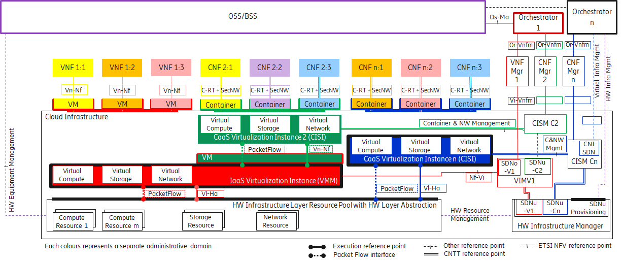
The Cloud Infrastructure Networking Reference Model depicted in Figure 4-7 is based on the ETSI NFV model enhanced with Container Virtualisation support and a strict separation of the HW Infrastructure and Virtualization Infrastructure Layers in NFVI. It includes all above concepts and enables multiple well separated simultaneous Virtualisation instances and domains allowing a mix of IaaS, CaaS on IaaS and CaaS on Bare Metal on top of a shared HW Infrastructure.
It is up to any deployment of the Cloud Infrastructure to decide what Networking related objects to use, but all Reference Architectures have to be able to map into this model.
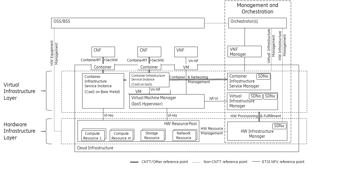
Figure 4-7: Networking Reference Model based on the ETSI NFV
4.3.3 Deployment examples based on the Networking Reference Model 
4.3.3.1 Switch Fabric and SmartNIC examples for Underlay Networking separation 
The HW Infrastructure Layer can implement the Underlay Networking separation in any type of packet handling component. This may be deployed in many different ways depending on target use case requirements, workload characteristics and available platforms. Two of the most common ways are: (1) within the physical Switch Fabric and (2) in a SmartNIC connected to the Server CPU being controlled over a management channel that is not reachable from the Server CPU and its host software. In either way the Underlay Networking separation is controlled by the HW Infrastructure Manager.
In both cases the Underlay Networking can be externally controlled over the SDNu interface that must be instantiated with appropriate Underlay Networking separation for each of the Virtualization administrative domains.
Note: The use of SmartNIC in this section is only pertaining to Underlay Networking separation of Virtual instances in separate Overlay domains in much the same way as AWS do with their Nitro SmartNIC. This is the important consideration for the Reference Model that enables multiple implementation instances from one or several Reference Architectures to be used on a shared Underlay Network. The use of SmartNIC components from any specific Virtual instance e.g. for internal virtual switching control and acceleration must be regulated by each Reference Architecture without interfering with the authoritative Underlay separation laid out in the Reference Model.
Two exemplifications of different common HW realisations of Underlay Network separation in the HW Infrastructure Layer can be seen in Figure 4-8 .
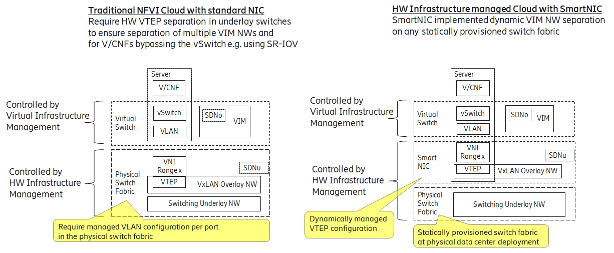
Figure 4-8: Underlay Networking separation examples
4.3.3.2 SDN Overlay and SDN Underlay layering and relationship example 
Two use case examples with both SDNo and SDNu control functions depicting a software based virtual switch instance in the Virtual Infrastructure Layer and another high performance oriented Virtual Infrastructure instance (e.g. enabling SR-IOV) are described in Figure 4-9 . The examples are showing how the encapsulation and mapping could be done in the virtual switch or in a SmartNIC on top of a statically provisioned underlay switching fabric, but another example could also have been depicted with the SDNu controlling the underlay switching fabric without usage of SmartNICs.
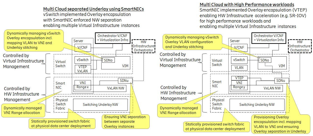
Figure 4-9: SDN Controller relationship examples
