3. High Level Architecture 

Table of Contents 
3.1 Introduction 
The CNTT Kubernetes Reference Architecture (RA) is intended to be an industry standard independent Kubernetes reference architecture that is not tied to any specific offering or distribution. No vendor-specific enhancements are required in order to achieve conformance to CNTT principles; conformance is achieved by using upstream components or features that are developed by the open source community. This allows operators to have a common Kubernetes-based architecture that supports any conformant VNF or CNF deployed on it to operate as expected. The purpose of this chapter is to outline all the components required to provide Kubernetes in a consistent and reliable way. The specification of how to use these components is detailed in Chapter 04 .
Kubernetes is already a well documented and widely deployed Open Source project managed by the Cloud Native Computing Foundation (CNCF). Full documentation of the Kubernetes code and project can be found at https://kubernetes.io/docs/home/ . The following chapters will only describe the specific features required by the CNTT Reference Architecture, and how they would be expected to be implemented. For any information related to standard Kubernetes features and capabilities, refer back to the standard Kubernetes documentation.
While this reference architecture provides options for pluggable components such as service mesh and other plugins that might be used, the focus of the reference architecture is on the abstracted interfaces and features that are required for telco type workload management and execution.
Chapter 5 of the Reference Model (RM) describes the hardware and software profiles that are descriptions of the capabilities and features that the Cloud Infrastructure provide to the workloads. As of v2.0, Figure 5-3 in the RM (also shown below) depicts a high level view of the software profile features that apply to each instance profile (Basic and Network Intensive). For more information on the instance profiles please refer to RM Chapter 4, section 4.2.4 .
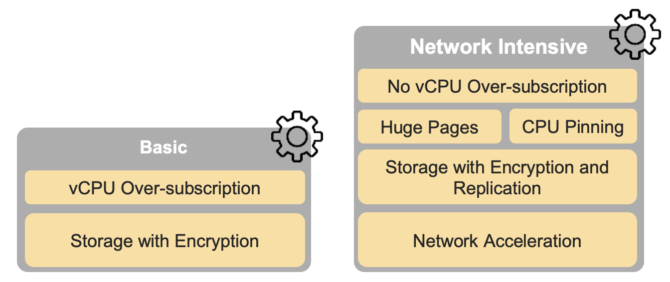
Figure 5-3 (from RM): NFVI software profiles
In addition, the RM Figure 5-4 (shown below) depicts the hardware profile features that apply to each instance profile.
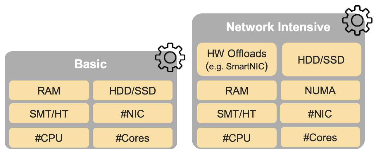
Figure 5-4 (from RM): NFVI hardware profiles and host associated capabilities
The features and capabilities described in the software and hardware profiles are considered throughout this RA, with the RA requirements traceability to the RM requirements formally documented in chapter 2, section 2.2 of this RA.
3.2 Infrastructure Services 
This chapter shall list the services provided by the infrastructure. Some example of these services are: log collection, monitoring, health check, load balancer. For the sake of clarity CaaS services should be also listed, like container lifecycle management or networking services.
3.2.1 Container Compute Services 
The primary interface between the Physical / Virtual Infrastructure and any container-relevant components is the Kubernetes Node Operating System. This is the OS within which the container runtime exists, and within which the containers run (and therefore, the OS whose kernel is shared by the referenced containers). This is shown in Figure 3-1 below.

Figure 3-1: Kubernetes Node Operating System
The Kubernetes Node OS (as with any OS) consists of two main components:
- Kernel space
- User space
The Kernel is the tightly controlled space that provides an API to applications running in the user space (which usually have their own southbound interface in an interpreter or libraries). Key containerisation capabilities such as Control Groups (cgroups) and namespaces are kernel features, and are used and managed by the container runtime in order to provide isolation between the user space processes, which would also include the container itself as well as any processes running within it. The security of the Kubernetes Node OS and its relationship to the container and the applications running within the container or containers is essential to the overall security posture of the entire system, and must be appropriately secured to ensure processes running in one container cannot escalate their privileges or otherwise affect processes running in an adjacent container. An example and more details of this concept can be found in chapter 6 ).
It is important to note that the container runtime itself is also a set of processes that run in user space, and therefore also interact with the kernel via system calls. Many diagrams will show containers as running on top of the runtime, or inside the runtime. More accurately, the containers themselves are simply processes running within an OS, the container runtime is simply another set of processes that are used to manage these containers (pull, run, delete, etc.), and the kernel features required to provide the isolation mechanisms (cgroups, namespaces, filesystems, etc.) between the components.
3.2.1.1 Memory management 
The Reference Model requires the support of Huge Pages in
i.cap.018
which is
already supported by upstream Kubernetes. For some applications, Huge Pages
should be allocated to account for consideration of the underlying HW topology.
This newer feature is missing from Kubernetes, therefore a gap has been
identified and added to
Chapter 6.2.8
3.2.1.2 HW Topology management 
This chapter should describe considerations about hardware topology management.
3.2.1.3 HW Acceleration 
This chapter should describe considerations about hardware acceleration, like device management.
3.2.1.5 Container Runtime Services 
The Container Runtime is the component that runs within a Kubernetes Node Operating System (OS) and manages the underlying OS functionality, such as cgroups and namespaces (in Linux), in order to provide a service within which container images can be executed and make use of the infrastructure resources (compute, storage, networking and other I/O devices) abstracted by the Container Host OS, based on API instructions from the kubelet.
There are a number of different container runtimes. The simplest form, low-level container runtimes, just manage the OS capabilities such as cgroups and namespaces, and then run commands from within those cgroups and namesapces. An example of this type of runtime is runc, which underpins many of the higher-level runtimes and is considered a reference implementation of the Open Container Initiative (OCI) runtime spec . This specification includes details on how an implementation (i.e. an actual container runtime such as runc) must, for example, configure resource shares and limits (e.g. CPU, Memory, IOPS) for the containers that Kubernetes (via the kubelet) schedules on that host. This is important to ensure that the features and capabilities described in chapter 5 of the RM are supported by this RA and delivered by any downstream Reference Implementations (RIs) to the instance types defined in the RM.
Where low-level runtimes are used for the execution of a container within an OS, the more complex/complete high-level container runtimes are used for the general management of container images - moving them to where they need to be executed, unpacking them, and then passing them to the low-level runtime, which then executes the container. These high-level runtimes also include a comprehensive API that other applications (e.g. Kubernetes) can use to interact and manage the containers. An example of this type of runtime is containerd, which provides the features described above, before passing off the unpacked container image to runc for execution.
For Kubernetes the important interface to consider for container management is the Kubernetes Container Runtime Interface (CRI) . This is an interface specification for any container runtime so that it is able to integrate with the kubelet on a Kubernetes Node. The CRI decouples the kubelet from the runtime that is running in the Host OS, meaning that the code required to integrate kubelet with a container runtime is not part of the kubelet itself (i.e. if a new container runtime is needed and it uses CRI, it will work with kubelet). Examples of this type of runtime include containerd (with CRI plugin) and cri-o, which is built specifically to work with Kubernetes.
To fullfill
req.inf.vir.01
the architecture should support a container runtime
which provides the isolation of Operating System kernels.
The architecture must support a way to isolate the compute resources of the infrastructure itself from the workloads compute resources.
3.2.2 Container Networking Services 
As all production networking solutions for Kubernetes are based on CNI plugins and the implicit requirement in 4.2.2 Virtual Network Interface Specifications that documents the requirement to have the capability to attach several network interfaces to the pods, the CNTT architecture must support a CNI metaplugin/CNI multiplexer.
A CNI metaplugin/CNI multiplexer has the capability to attach several interfaces, using different other CNI plugins, to a pod. Note that the different network characteristics of the interfaces might require different networking technologies, which would potentially require different CNI plugins.
To comply with
req.inf.ntw.08
, inter node communication must be served by a
CNI plugin which complies with the default
Kubernetes networking assumptions
.
There are two types of low latency and high throughput networks required by telco workloads: signalling traffic workloads and user plane traffic workloads. Networks used for signalling traffic are more demanding than what a standard overlay network can handle, but still do not need the use of user space networking. Due to the nature of the signalling protocols used, these type of networks require NAT-less communication documented in infra.net.cfg.003 and will need to be served by a CNI plugin with IPVLAN or MACVLAN support. On the other hand, the low latency, high throughput networks used for handling the user plane traffic require the capability to use a user space networking technology.
Note: An infrastructure can provide the possibility to use SR-IOV with DPDK as an additional feature and still be conformant with CNTT.
Editors note: The possibility to SR-IOV for DPDK is under discussion.
The integration of SDN solutions required by
req.inf.ntw.05
should be enabled
via their respective CNI integration.
Note: An SDN solution can manage the pod networks via the Kubernetes API or can have a CNI integration.
The container based architecture must support telecom equipment networking where
the CNF networks are set up by the operator’s network administrators. This is
why, as
req.gen.cnt.05
requires, the architecture must provide a set of
abstract management APIs to manage the network connectivity of the CNF pods
themselves.
The API must support multiple tenants and must require elevated access rights to manipulate infrastructure related API objects as these operations generally require reconfiguration of the physical network infrastructure.
To fulfill the requirements of
e.cap.016
the architecture should optionally
support the use of device plugins via the Device Plugin API and the alignment of
the devices, CPU topology and Huge Pages must be supported using the
Topology
Manager
.
The architecture must support IPv4, IPv6 and dual stack interfaces of the
workloads as required by
req.inf.ntw.04
.
As Kubernetes Ingress, Egress and Services have no support for all the protocols needed in telecommunication environments (Diameter, SIP, LDAP, etc) and their capacity is limited, the architecture must enable the use of alternative load balancers, including external or ones built into the application. Management of external load balancers must be possible via Kubernetes API objects.
The well known service meshes are “application service meshes” that address and interact with the application layer 7 protocols (eg.: HTTP) only. Therefore, their support is not required in this architecture, as these service meshes are outside the scope of the infrastructure layer of the CNTT stack.
3.2.3 Container Storage Services 
Since its 1.13 version Kubernetes supports Container Storage Interface (CSI) in production and in-tree volume plugins are moved out from the Kubernetes repository (see a list of CSI drivers here ).
Running containers will require ephemeral storage on which to run themselves (i.e. storage on which the unpacked container image is stored and executed from). This ephemeral storage lives and dies with the container and is a directory on the worker node on which the container is running. Note, this means that the ephemeral storage is mounted locally in the worker node filesystem. The filesystem can be physically external to the worker node (e.g. iSCSI, NFS, FC) but the container will still reference it as part of the local filesystem.
Additional storage might also be attached to a container through the use of Kubernetes Volumes - this can be storage from the worker node filesystem (through hostPaths - not recommended), or it can be external storage that is accessed through the use of a Volume Plugin. Volume Plugins allow the use of a storage protocol (e.g. iSCSI, NFS) or management API (e.g. Cinder, EBS) for the attaching and mounting of storage into a Pod. This additional storage, that is attached to a container using a Kubernetes Volume, does not live and die with the container but instead follows the lifecycle of the Pod that the container is a part of. This means the Volume persists across container restarts, as long as the Pod itself is still running. However it does not necessarily persist when a Pod is destroyed, and therefore cannot be considered suitable for any scenario requiring persistent data. The lifecycle of the actual data depends on the Volume Plugin used, and sometimes the configuration of the Volume Plugin as well.
For those scenarios where data persistence is required, Persistent Volumes (PV) are used in Kubernetes. PVs are resources in a Kubernetes Cluster that are consumed by Persistent Volume Claims (PVCs) and have a lifecycle that is independent of any Pod that uses the PV. A Pod will use a PVC as the volume in the Pod spec; a PVC is a request for persistent storage (a PV) by a Pod. By default, PVs and PVCs are manually created and deleted.
Kubernetes also provides an object called Storage Class, which is created by cluster administrators and maps to storage attributes such as quality-of-service, encryption, data resilience, etc. Storage Classes also enable the dynamic provisioning of Persistent Volumes (as opposed to the default manual creation). This can be beneficial for organisations where the administration of storage is performed separately from the administration of Kubernetes-based workloads.
There are no restrictions or constraints that Kubernetes places on the storage that can be consumed by a workload, in terms of the requirements that are defined in RM sections 5.2.2 (software) and 5.4.2 (hardware). The only point of difference is that Kubernetes does not have a native object storage offering, and addressing this capability gap directly is outside of the scope of this RA.
3.2.4 Kubernetes Application package manager 
To manage complex applications consisting of several Pods the Reference Architecture must provide support for a Kubernetes Application package manager. The Package Manager would be able to manage the lifecycle of a set of Pods and provide a framework to customise a set of parameters for their deployment. The requirement for this Reference Architecture is to provide a Kubernetes API that complies with the CNCF Conformance test for the package managers to use in the lifecycle management of the applications they manage. The Reference Architecture does not recommend the usage of a Kubernetes Application package manager with a server side component installed to the Kubernetes cluster (e.g.: Tiller).